|

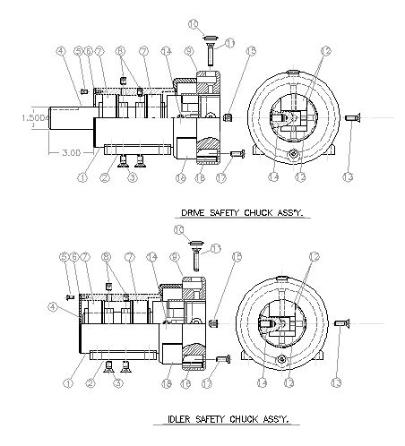
- 1 - Remove the 2 socket head set screws (item 8) from the top of the shaft holder housing. This will allow access to locking screws of the 2 bearings (item 7) mounted internally.
- 2 - Rotate the locking collar (item 9) or drive shaft (item 4) to align the bearing locking screws in each access hole. There are 2 locking screws on each bearing inner race. Loosen each of the screws and then extract the drive or idler shaft and locking collar assembly. Please note the small gap between the top of the housing and the locking collar (approximately 1/64', just free enough to keep collar and housing from making contact). The assembly should be replaced in the same relative position.
- 3 - Item 16 is a (brass) collar actuator that automatically closes the locking collar if not done manually. With the shaft and locking collar assembly removed from the housing the collar actuator (part #39269-10) will be exposed for inspection. If replacement is needed remove the button head cap screw (item 17) to extract the collar actuator. Replace the collar actuator with its flat side toward the outer diameter of the locking collar (item 9) and reassemble the shaft and locking collar assembly in the housing.
Converter Accessory Corporation
201 Alpha Road
Wind Gap, PA 18091
(800) 433-2413
Fax: (800) 709-1007
email: cac@epix.net
|
