IMPORTANT:
- READ THESE INSTRUCTIONS ENTIRELY BEFORE INSTALLING THE WrinkleSTOP® ROLL.
- DO NOT LAY ROLL ON ITS FACE AS IT WILL CAUSE A FLAT SPOT AND/OR OTHER DAMAGE TO THE OUTER SLEEVE AND/OR THE INTERNAL CONSTRUCTION.
- ALWAYS SUPPORT THE ROLL ON THE CENTER SHAFT ONLY.
WrinkleSTOP® OPERATING PRINCIPLE
The WrinkleSTOP® No-Bow Spreader Roll is essentially a dead shaft idler roll. The face of the roll is made up of a rubber sleeve, the ends of which are attached to ball bearings mounted to adjustable pivoting end caps. The sleeve is supported by a series of flexible disks which are mounted to a ball bearing mounted support tube.
The outer sleeve, disks, end caps and disk support tube all rotate together about a common center support shaft.
During the course of one revolution, the outer sleeve stretches from zero to preset stretch in 180 degrees and relaxes from preset stretch to zero in the remaining 180 degrees.
RULES OF THUMB
There are four basic considerations that affect the spreading action of a WrinkleSTOP® Roll. They are:
- Lead In Distance
- ∗The longer the lead in, the greater the spreading. Typically, the lead in should be double the lead out.
- Wrap Angle
- ∗The more wrap (180 degrees maximum) the greater the spreading.
- End Caps
- ∗The more angular displacement (5 degrees maximum) the greater the spreading.
- Sleeve Stretch
- ∗The Multi-Adjust® WrinkleSTOP® has an adjustable sleeve stretch feature that allows for the optimum setting to suit your application. See "Setting the sleeve stretch" section.
When the end caps are parallel to the flow of material, a zero spreading condition exists. Angular displacement of the end caps will regulate the amount of spreading action.
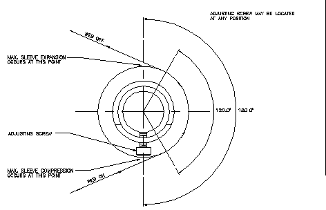
The end caps are independently adjustable allowing for differential spreading from one side of the web to the other. Adjustment is made with Adjusting Screw 10 (see figure B).
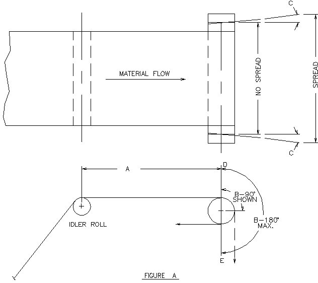
A= LEAD IN
B= WRAP ANGLE
C= END CAP ANGULAR DISPLACEMENT
D= SLEEVE @ ZERO STRETCH
E= SLEEVE @ MAX. STRETCH
Figure A
As seen in Figure A spreading action will occur if the material enters the roll at point D and leaves the roll at point E. It is best to enter the roll slightly downstream of point D and exit just prior to point E.
NOTE: The roll will spread with any wrap angle, 180 degrees is not required for every application. (see table)
Spreading Action Table |
| Wrap angle | % End Cap Displacement
| % Spread
|
90 deg | 0 | 0 |
| 50 | 25 |
| 100 | 50 |
120 - 180 deg | 0 | 0 |
| 50 | 50 |
| 100 | 100 |
|
The roll may be oriented so the stretch / relax cycle will occur wherever the machine design and/or material flow dictates. The center shaft is supported in split pillow block mounting brackets on each end. The spread position can be adjusted by loosening the top cap bolt in each bracket and rotating the center shaft.
BE SURE TO RETIGHTEN THESE BOLTS WHEN THE ADJUSTMENT HAS BEEN COMPLETED.
The two mounting brackets each have two slotted mounting holes to facilitate mounting to the existing machine frame.
Click on image to enlarge
(FIGURE B)
Click on image to enlarge
SETTING THE SLEEVE STRETCH
THE AMOUNT OF SLEEVE STRETCH FOR YOUR MULTI-ADJUST WRINKLESTOP HAS BEEN FACTORY PRESET FOR OPTIMUM PERFORMANCE WITH YOUR OPERATING SPECIFICATIONS. YOU SHOULD NOT HAVE TO ADJUST THE SLEEVE STRETCH.
IMPORTANT
DO NOT ADJUST PIVOT SLIDER ADJUSTING SCREW (#20). THIS ADJUSTMENT HAS BEEN PRE-SET FOR YOUR SPECIFICATIONS. SEE "RUBBER SLEEVE REPLACEMENT INSTRUCTIONS" IF RE-ADJUSTMENT IS REQUIRED.
DO NOT LAY ROLL ON ITS FACE AS THIS WILL CAUSE A FLAT SPOT AND/OR OTHER DAMAGE TO THE OUTER SLEEVE AND/OR THE INTERNAL CONSTRUCTION.
ALWAYS SUPPORT THE ROLL ON THE CENTER SHAFT ONLY.
Manufactured under U. S. Patent No. 4862565 t.m. reg. US pat. & tm office
| 


