News


CAC Products >>> Anti-wrinkle devices  >>> Latest news on our Anti-Wrinkle Devices

Wrinkle Removal

CAC Expands Anti-Wrinkle Product Line with Introduction of Bowed Roll

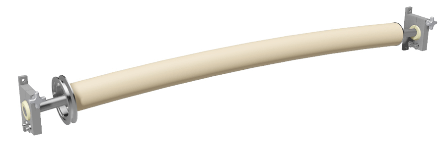
Converter Accessory Corporation (CAC) is introducing bowed rolls to its’ already extensive line of anti-wrinkle technology and devices. The new model FB350 bowed roll utilizes fixed bow technology, engineered to fit customers’ specific application(s). Fixed bow provides excellent aggressive, repeatable performance for the most demanding anti-wrinkle applications. It is also extremely well suited to separate slit widths for slitter rewinder applications, to prevent interleaving.

The FB350 is currently available in versatile 3.5” diameter and face widths up to 70”. Drive sheaves are available for light tension applications. Rubber sleeve material may be varied where high heat, chemicals, adhesives or excessive ozone exposure may be a concern. Optional mounting blocks, designed for use with the FB350, allow for optimal bow placement in any application.

According to Jeff Damour, CAC engineering manager, the inclusion of bowed rolls to an extensive anti-wrinkle product offering greatly enhances CAC’s ability to offer complete standard and customized solutions to eliminate web wrinkles in any converting process. The new FB350 bowed roll will join WrinkleSTOP, Multi-Adjust WrinkleSTOP, Adjusta-Pull, Angular Adjusta-Pull bracket, Scroll Roll and crowned and concave rollers to accommodate a truly complete and unique array of solutions to combat web wrinkles.

FB350 bowed rolls are acceptable for use with textiles, all types of plastic films, paper and non-wovens. They can be used in applications from slow speed to high speed, narrow web to wide web. More information can be found at FB350 3.50 diameter Bowed Roll


CAC Adds Adjustable Mounting Bracket to Adjusta-Pull® Anti-Wrinkle System

Converter Accessory Corporation’s (CAC) NEW adjustable mounting bracket is the perfect value added option for use with CAC’s Adjusta-Pull® anti-wrinkle system.

According to Jeff Damour, CAC Engineering Manager, this new mounting bracket includes a cantilevered extruded aluminum slide rail frame allowing easy web width adjustment. The hand operated angle adjustment knob makes for easy side to side tuning of anti-wrinkle action.

Four bolt mounting makes these mounting brackets extremely easy to mount. They may be purchased to accompany any new Adjusta-Pull applications or added to existing Adjusta-Pull nip type anti-wrinkle systems in the field. Simple, one bolt mounting of the Adjusta-Pull® system to the bracket is all that is required.

Damour said: "We have designed these mounting brackets with ease of installation and versatility of use in mind. I highly recommend this mounting system for any Adjusta-Pull® anti-wrinkle application, new or already existing."

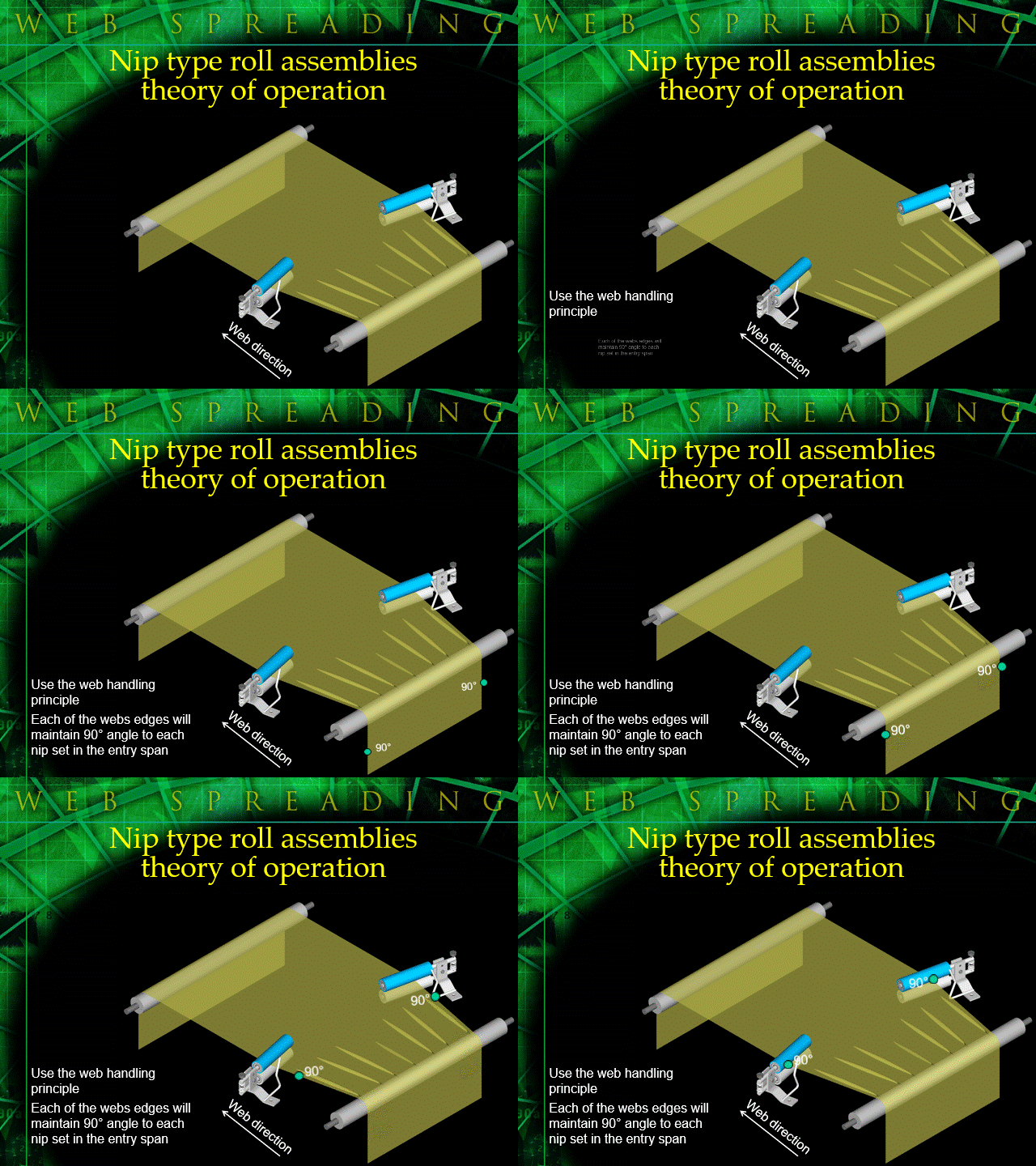
Adjusta-Pull® nip type anti-wrinkle systems employ two opposing nip roll assemblies that are mounted to each edge of the web. The nip assemblies are angled away from each other. Each web edge will attempt to maintain a 90 degree entry angle to each Adjusta-Pull® nip assembly effectively pulling on each edge of your web, removing wrinkles. The system is a very simple answer to the very complex and expensive problem of web wrinkles.


Thin webs without wrinkles

Any converter running webs of thin- and ultra-thin gauge material, including foil, may experience wrinkle problems. In general, there are at least two excellent solutions to wrinkle problems, but only one-expanding surface spreader rolls-is the preferred choice for converters running thin gauges. Expanding surface spreader rolls have proven to provide the best wrinkle removal for virtually any application in web widths 3-120 in. They are effective in any printing, coating, or laminating operation, and their performance is especially noteworthy when applied to thin-gauge film and foil.

Studying the Systems

An impartial examination and evaluation of the performance of all wrinkle-removing systems came in a definitive study published in a bound edition, edited by J.K. Good, of the Fourth Intl. Conference of Web Handling, held June 1-4, 1997, at the Web Handling Research Center, Oklahoma State Univ., Stillwater, OK. The specific study, “Testing and Analysis of Web Spreading and Anti-Wrinkle Devices” by R.P. Swanson, 3M Co., (pp414-428), found “the expanding surface rollers did not wrinkle under any test conditions. The regime I performance was excellent. This roller is an aggressive web-spreading device. An expanding surface roller would be insensitive to wrinkles at low, medium, and high tensions. This roller is an excellent, high drag, web spreading and anti wrinkle device.” (p421). Of the ten types of systems tested, only the expanding surface spreader rolls and the “curved axis” or bowed roll systems were described as “excellent” systems according to the study.

The single distinguishing drawback of bowed spreader rolls, compared to expanding surface spreader rolls, is the potential web-distorting effect built into the design (See Figures 1 and 2). The arc itself, the core of the design principle, has the potential of stretching and even tearing the center of the web. With many materials, depending on the amount of distortion, this may not be an issue. But with very thin gauges, as is often the case with foils and films, the capacity to absorb any distortion of materials is limited. Tears and stretching may result, and the impaired quality may be more noticeable than it might be with other materials.

Figure 1
Figure 2

When compared to bowed spreader rolls, the only other system to receive an “excellent” in the Swanson study, the expanding surface spreader roll is distinguished by its ability to maintain a constant tension profile while acting on the web.

Example Makes the Point

Let’s take a look at a typical expanding surface spreader roll. This example (same example as the Swanson study) employs a stretchable rubber sleeve supported by a series of rubber support disks. On each end of the sleeve, there are end collars mounted on bearings and an adjustable axle. The end collars clamp and hold the sleeve in place. Importantly, however, the end collars are canted to a mechanically adjustable degree, and it is this cant that provides the contracted and expanded pattern of the stretching section of the roll. (See Figures 3 and 4).

Figure 3
Figure 4

Essentially and simply, during production the web continually stretches from the short side of the rubber sleeve to the long side. The material enters the roll at the point where sleeve expansion begins and exits at a point prior to sleeve contraction. The desired spreading action is achieved without distortion of the web.

Wrinkle removal comes from the expanding action evenly distributed across the web. The amount of expansion may be adjusted at each end of the web – continually, if necessary – to compensate for distortions derived from changing up-stream conditions.

This type of spreader is an aggressive wrinkle-removal device. Spreading amount is adjustable from- 0%-100%. Adjustments can be made from each end of the roll while the machine is running. The recommended wrap angle for this roll is from 90°-180°, the greater the wrap angle, the greater the stretch.

For converters of thin-gauge materials, or where consistent gauge and unmarred surfaces are especially important, the expanding surface spreader roll maintains an even tension across the surface and does not distort or tear the center or edges of a web. Also, the smooth surface does not mar, scratch, or distort web surfaces.

Benefits Outweigh Flaws

With a couple of minor caveats (the system does not distribute the stretch across the web perfectly, and its effectiveness may be inhibited at extremely fast web speeds), the expanding surface spreader roll has proven to be the most effective wrinkle-removal system available for thin-gauge materials.

It is true almost every spreader roll will remove some level of wrinkles, and a converter’s selection of a system should be guided, in part, by the degree of wrinkle removal desired and, in part, by the amount of distortion converters and their customers can tolerate. While both bowed roll and expanding surface spreader rolls offer an excellent performance, when it comes to thin- and ultra-thin gauge materials and when quality is paramount, the expanding surface spreader roll is the preferred choice.

Jeff Damour is the engineering manager at Converter Accessory Corporation, Wind Gap, PA. He has been with CAC for 17 years and has published several technical articles covering a wide range of web handling applications. Jeff has the honor of presenting web spreading technology for converters at the Slitting and Rewinding Fundamentals and Coating and Laminating seminars run by Converting Equipment Mfrs. Assn. (CEMA). Contact Jeff at 800-433-2413; jdamour@converteraccessory.com. The views and opinions expressed in Technical Reports are those of the author(s), not those of the editors of PFFC. Please address comments to author(s).


Spreader Rolls Support Improved Sustainability of Web Produced Products

WrinkleSTOP® Spreader Rolls can help converters and their customers offer more sustainable products. WrinkleSTOP® has a proven ability to improve the quality of web production, reduce waste and effectively run thinner gauge materials.

With material costs skyrocketing and new demands for “greener” products converters are facing new challenges to their ability to compete profitably. Since the Wal-Mart sustainability scorecard went into effect in February, sustainability pressure on converters participating in the packaging markets has significantly increased. The “scorecard” is a comprehensive system that rates every aspect of a package's sustainability including materials, manufacturing techniques and shipping, and allows Wal-Mart to give shelf space preference to higher scoring products.

Jeff Damour, CAC Engineering Manager, said: “Strategically employed WrinkleSTOP® Spreader Rolls not only support down-gauging and thinner gauges while generating less waste, they also allow an overall increase in line speeds. Sustainable practices do not have to require compromises. They can also be good business practices. Our aim is to improve efficiency and increase sustainability without compromises in quality or profits.”

About WrinkleSTOP®

WrinkleSTOP® Spreader Rolls remove wrinkles with no web distortion, offer edge-to-edge adjustability, from 0% to 100% spread, while the web is in motion, require no special tools for adjustment and have a broad range of applications. WrinkleSTOP® Spreader Rolls improve overall versatility by extending the reach of materials that can be profitably run on most web operations. They are effective with laminating, slitting, printing, coating, textiles, paper, film and nonwoven production.

“WrinkleSTOP® Spreader Rolls accept many materials at any wrap angle, even with extremely short lead-in and lead-out web distances. It really shows off its' performance with thin gauge materials,” Damour said. “However, it works equally well with all materials and thickness”

In independent performance evaluation tests, WrinkleSTOP® Spreader Rolls removed all the wrinkles, all the time, under rigorous conditions and proved to be the best performer in a broad field of subjects. WrinkleSTOP® Spreader Rolls offer both standard and custom sleeves to match most applications and features high-quality motor-grade bearings.


Industry Leading Converter to test WrinkleSTOP® 3000

Converter Accessory Corporation (CAC) has produced a WrinkleSTOP® 3000 for beta installation in a fortune 500 company. The new WrinkleSTOP® 3000 anti-wrinkle rolls are engineered to be compatible with web production speeds up to 3000 feet per minute, doubling the speed capabilities of previous versions. WrinkleSTOP® 3000 anti-wrinkle rolls are available in 8 inch diameters and widths up to 200 inches. The 8 inch diameter, 72 inch face beta version is custom engineered to match the customer's requirements.

More than 2000 previous versions of WrinkleSTOP® are successfully in use in North America. In addition to improving quality and significantly reducing scrap, in some cases to zero, WrinkleSTOP® anti-wrinkle rolls have consistently allowed an overall increase in line speeds.

According to Jeff Damour, Engineering Manager, WrinkleSTOP® anti-wrinkle rolls remove wrinkles with no web distortion, offer edge-to-edge adjustability, from 0% to 100% spread, while the web is in motion, require no special tools for adjustment and have a broad range of applications. WrinkleSTOP® anti-wrinkle rolls improve overall versatility by extending the reach of materials that can be profitably run on most web operations. WrinkleSTOP® anti-wrinkle rolls are effective with laminating, slitting, printing, coating, textiles, paper, film and nonwovens production.

In a recent independent performance evaluation test, WrinkleSTOP® anti-wrinkle rolls removed all the wrinkles, all the time, under rigorous conditions and proved to be the best performer in a broad field of subjects. All WrinkleSTOP® anti-wrinkle rolls offer both standard and custom sleeves to match most applications and feature high-quality motor-grade bearings.

”Most converters are always interested in technology that will allow them to go thinner, faster and wider. Our newest WrinkleSTOP® anti-wrinkle rolls were developed to match these demands for top performance at high speeds in wider webs. WrinkleSTOP®, in all configurations, remains the best wrinkle removing upgrade for web processing under all conditions, including the widest range of materials at any wrap angle, even those with extremely short lead-in and lead-out web distances,“ Damour said.

Currently celebrating its 32nd year of success, Converter Accessory Corporation designs, engineers and manufactures web handling equipment for converters of paper, film, foil, nonwovens and textiles. Engineered solutions include high quality, cost effective equipment from the simplest aluminum core cone to the most sophisticated unwind/rewind system. CAC is represented by knowledgeable sales engineers and provides extensive consultation and post sales support.

For more information contact Jeff Damour, Converter Accessory Corporation, 201 Alpha Road, Wind Gap, PA 18091-1279, (800) 433 2413, fax (610) 863 7818, or click above to chat with an on-line sales engineer.

Written By: Jeff Damour, Sales Manager, Converter Accessory Corporation, Wind Gap, PA
Phone - 800-433-2413

Web Spreading System Employs Simple Principle for Effective, Economical Results

Converter Accessory Corporation's (CAC) new Adjusta-Pull® web spreading system is a remarkably efficient and cost effective approach to wrinkle removal and web spreading. Adjusta-Pull is an aggressive system, especially effective with nearly all textiles and nonwovens as well as paper and film applications.

According to Pam Damour, CAC General Manager, the entirely mechanical system employs the web principle that a web will seek a 90° angle to a roll in its entry span to that roll.

Adjusta-Pull® consists of two opposing nip roll assemblies that use this principle to impose a consistent, controlled outward draw on the web material. Easily adjusted angular displacement, relative to the direction of the web flow, influences the amount of draw and thus allows regulation of the amount of spreading action.

Ball bearing mounted Adjusta-Pull® nip rolls in nine and six inches come in standard one rubber/ one aluminum configurations, but may be supplied with virtually any covering, including plasma, silicone, urethane, Teflon, etc., for spreading materials with special requirements.

For additional web spreading, Adjusta-Pull® can be arranged in sequences of multiple pairs.

Damour said: ”This is a reliable web spreading system that is easy to install, requires little maintenance, consumes no energy and delivers an exceptionally fast return on investment. We have so much confidence in this system that we offer trial installations to qualified customers.“

In addition to Adjusta-Pull®, CAC has several other types of wrinkle removal systems, including the widely successful WrinkleSTOP®. CAC's product diversity allows customers to select optimal wrinkle removal technology for each application.

Founded in 1974, Converter Accessory Corporation designs, engineers and manufactures web handling equipment for converters of paper, film, foil, nonwovens and textiles. Engineered solutions include high quality, cost effective equipment from the simplest aluminum core cone to the most sophisticated unwind/rewind system. CAC is represented by knowledgeable sales engineers and provides extensive consultation and post sales support.

For more information contact Pam Damour, Converter Accessory Corporation, 201 Alpha Road, Wind Gap, PA 18091-1279, (800) 433 2413, fax (610) 863 7818. cac@epix.net Web site: www.handleyourweb.com


FOX Runner™ Portable Pneumatic Waste Removal System

Ready to run in 15 minutes, roll in place and hook up power!

 
CAC portable systems are shipped completely assembled and ready to use. As with all FOX TrimAway systems, FOX Runner has a unique venturi at its heart. Teamed with a powerful, efficient and quiet regenerative blower, FOX Runner is able to generate suction and pressure air streams to pick up and convey your edge trim, die cut pieces or matrix from your machine.
  • Turn Key for fast and easy installation and operation
  • Portable for operation at different stations
  • Systems available to discharge over 100 feet
  • Energy efficient
  • Systems available to handle up to two 6 inch wide trims, up to 6,000 FPM
  • Click here for additional information!
Efficiently remove paper, film, foil, textile and non-woven trims. Great for picking up and removing pieces (die cutter) as well as chopped, granulated and palletized materials.
 

Click here to see our products


COMMON ANTI-WRINKLE SYSTEMS

Nip Type (each edge of the web) Spreader Roller System

Description:

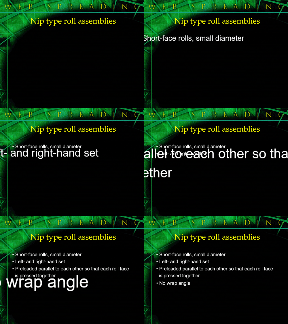
Nip type spreader rollers are normally short face rollers (less than 12” face) and small diameter (less than 3” diameter). These rollers are supplied in a left and right hand set. Each set consists of 2 rollers pre-loaded so each roller face is pressed together; these roller faces must be parallel with each other. Each roller set is very similar in design to other nip rollers used in converting (such as drive nips). One of the rollers in each set must be rubber covered (for traction); sometimes both rollers in the set are rubber covered.

Theory of operation:

The left and right side nip sets are mounted to the machine frame and each edge of the web is fed through the nip rollers. The left and right side nip roller sets are then angled away from each other, facing in the down stream direction. Because of the web handling principle, that a web will seek to align itself perpendicular to a roller, in its entry span to that roller, each web edge will seek to be perpendicular to each nip roller set. This type of spreader roller is extremely aggressive and will remove more web wrinkles, more aggressively than any other type of anti-wrinkle system.

This type of spreader roller has no wrap angle. Because the web is not supported across its full width, the material must be fed straight in and out of this spreader roller assembly.

No alt text provided for this image

Main advantages:

● This type of anti-wrinkle system is the most aggressive.

● Simplicity of design makes this type of spreader roller easy to maintain.

● The amount of spreading is easily adjustable, by changing the angle of each nip set independently of each other.

Main disadvantage:

● Because this anti-wrinkle system does not support the web across its full width, it may mark or distort foils. Typically, this anti-wrinkle system is not used with foil webs.

Bowed rollers

Description:

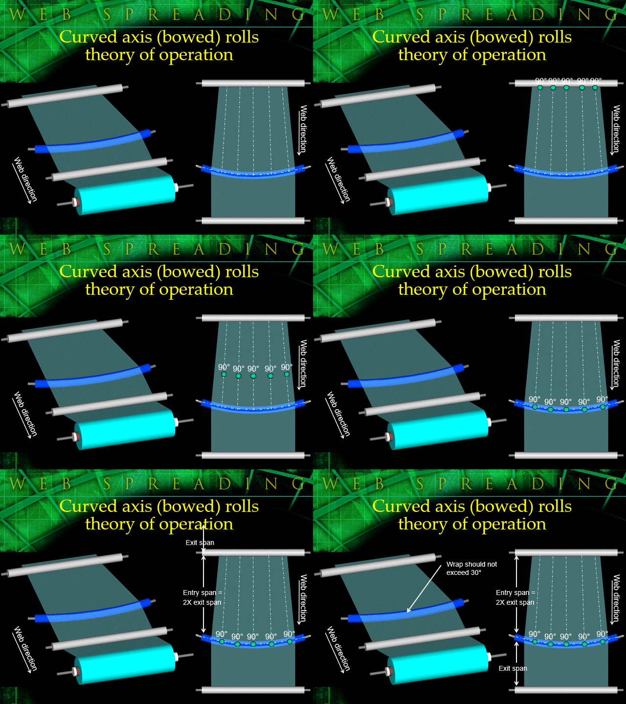
A bowed roller is manufactured exactly as the name states – the center axle of the roller is bowed (not linear). A series of internal ball bearings, supported by the axle, in turn support a rubber sleeve which is continuous across the bowed roller face. The amount of curve (bow) in the roller face is application dependent and is available in both an adjustable and non-adjustable versions.

Theory of operation:

This roller works based on two different web spreading principles.

First, as we know, a web will seek to align itself perpendicular to this roller (as long as it is in traction with the roller). This causes the web to spread at any given interval across its width as it tries to maintain the 90° tangent points across the curved axis of the bowed roller face width.

Second, the rubber sleeve, which spans the roller face, is narrower on the entry side of the roller than the exit side, so as it rotates, the rubber sleeve stretches and the material, laying on top of the rubber surface, stretches with the rubber sleeve.

Because this roller normally operates best with minimal wrap angle, the first spreading principal does most of the work. Less surface contact between the web and the rubber sleeve means less stretching principal will effect overall spreading. However, the spreading based on web handling principle is hardly affected by wrap angle.

No alt text provided for this image

Recommended wrap angle is usually less than 30°. Many times, when it appears a bowed roller is not operating properly, this is due to wrap angles to great for the application. More important than wrap angle, lead-in and lead-out distances are critical. Typical lead-in (entry span) to the curved axis (bowed) roller should be approximately double the lead-out distance (exit span). As you can see in the illustration, most of the spreading caused by this roller is done in the entry span to this roller, so the longer the entry span is, the more web wrinkles will be eliminated. The exit span should be kept short so the web stays spread. The longer the exit span is, the more chance there is for the spreading affect to be lost (or the web may return to its wrinkled or natural state).

Main advantages:

● This type of spreader roller is an aggressive anti-wrinkle device.

● Bowed rollers are very common. They are accepted for all facets of converting from narrow web to wide web (it is especially used in wide web applications) and slow speed to high speed.

● This type of spreader roller is used with all types of webs in all types of converting processes.

● This roller has a smooth surface, so it will not mark or scratch the surface of the web.

Main disadvantages:

● Bowed rollers are not linear, so they can permanently distort the center of some webs. Because web tension is not evenly distributed across the face of bowed rollers, added tension delivered to the center of the web (due to curved shape of the bowed roller) may cause this distortion.

● When maintenance is required this roller is normally returned to the bowed roller manufacturer.

● Because the rubber sleeve is dynamic (it constantly stretches and contracts with each revolution) the rubber sleeve does wear over time.

Expanding Surface Anti-Wrinkle Roller 

Description:

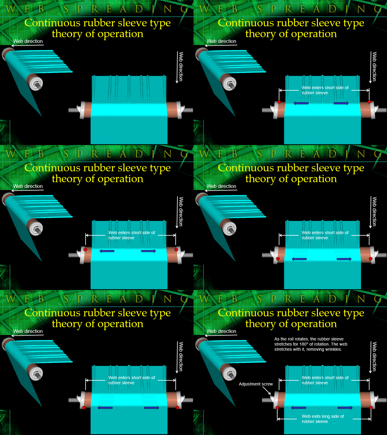
This type of anti-wrinkle roller is manufactured with a rubber sleeve stretched across its face. On each end of the rubber sleeve there are end collars that clamp and hold the sleeve in place. The end collars are mounted on bearings and an adjustable axle. The sleeve is mounted across a series of flexible rubber disks. The rubber sleeve and end caps rotate together.

Theory of operation:

This roller must be incorporated as a dead shaft idler roller, in order to operate properly. The continuous rubber sleeve is pre-loaded across the face of the roller. The end collars are clamped on to each end of the rubber sleeve. The end collars are then canted with an adjustment screw and flange-axle assembly. The canting adjustment is designed so that the collars are facing each other on one side of the roller face and they are away from each other on the opposite (180°) side of the roller. The continuous rubber sleeve stretches from the point where the collars are facing each other, to where the collars are away from each other. The sleeve then contracts for the next 180° of rotation, from where the end collars are facing away from each other to where they are facing toward each other. Bottom line, the rubber sleeve physically stretches from the short side of the rubber sleeve to the long side of the rubber sleeve, then contracts again. The web enters the contracted side of the rubber sleeve and exits on the expanded side. As this roller rotates, the stretching action of the rubber sleeve eliminates wrinkles from the web.

No alt text provided for this image


Recommended wrap angle for this roller is from 90° to 180°. More wrap (up to 180° maximum) means more wrinkle removal. The amount of web spreading is directly proportional to the amount of wrap angle. In other words 180° of wrap will provide for 100% of possible spreading, 90° of wrap will provide 50% of possible spreading, 45° of wrap will provide 25% of possible spreading, etc. Lead-in and lead-out distances are not critical in the application of this type of anti-wrinkle device, because all or most of the web spreading is taking place on the roller face, not in the entry span to the roller.

Main advantages:

● This type of anti-wrinkle system is an aggressive wrinkle eliminating device.

● Anti-wrinkle aggression is adjustable from 0% (no spreading) - 100%. Adjustment can be made while the web is running with standard tools. Each side of the roller is independentally adjustable.

● This roller is linear across its face, so tension remains evenly distributed across the roller face. So, this roller will not distort your web.

● Roller surface is smooth and linear so it will not mark, scratch or deform a web.

● This roller is used with all types of webs.

Main disadvantages:

● Web speeds are a consideration when utilizing this roller. If the web speed causes the sleeve to balloon, as a result of centrifugal force, then the roller may not operate properly.

● The sleeve is stretching and contracting with every revolution, so the continuous rubber sleeve will degrade over time.

Written By: Jeff Damour

How Open Loop Tension Controls Work

  • Published on January 3, 2023

How do open loop tension controls work?

First, a word about the term drive.

In many of the descriptions throughout this presentation I refer to the term “drive”. I am using this term as a purely generic term to describe a mechanical device that delivers torque to a roll of material or driven roll(s) in a converting machine. This device could be a motor, brake or clutch. This presentation is not meant to detail drive mechanisms; instead its intent is to describe the fundamental mechanics of tension control systems.

Manual tension control.

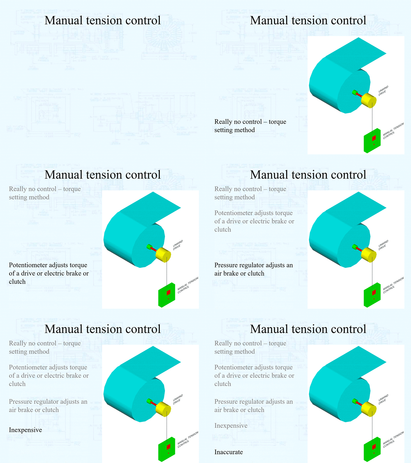
The simplest and least expensive method of tension control is manual. They can be as simple as a potentiometer adjusting the torque output of a drive or magnetic particle brake or clutch or an air regulator adjusting the air pressure and therefore torque output of an air brake or clutch. This control method can be used in all three tension zones. Obviously, it is the least accurate of all types of tension controls because it relies completely on operator “feel” to set the proper tension. There is no feedback from the machine to verify any actual process tension levels. Often times they will have some sort of “meter” on the front of the control to display output as a reference point.

Unwind and rewind tension zones are the most difficult to control manually because of constantly changing diameters and therefore need to be constantly adjusted. 

No alt text provided for this image

Diameter measurement control.

There are several types of diameter measurement controls. Each type has its own method of sensing the unwind and rewind roll diameter. These controls are extremely useful for controlling the tension off an unwind and onto a rewind. However, because they control tension by proportionally decreasing (unwind) or increasing (rewind) torque relative to roll diameter change, they do not work for internal tension zones. These types of tension controls are used strictly at the unwind and rewind tension zones. These controls can be supplied with taper tension for rewind zone applications.

Diameter measurement control – follower arm.

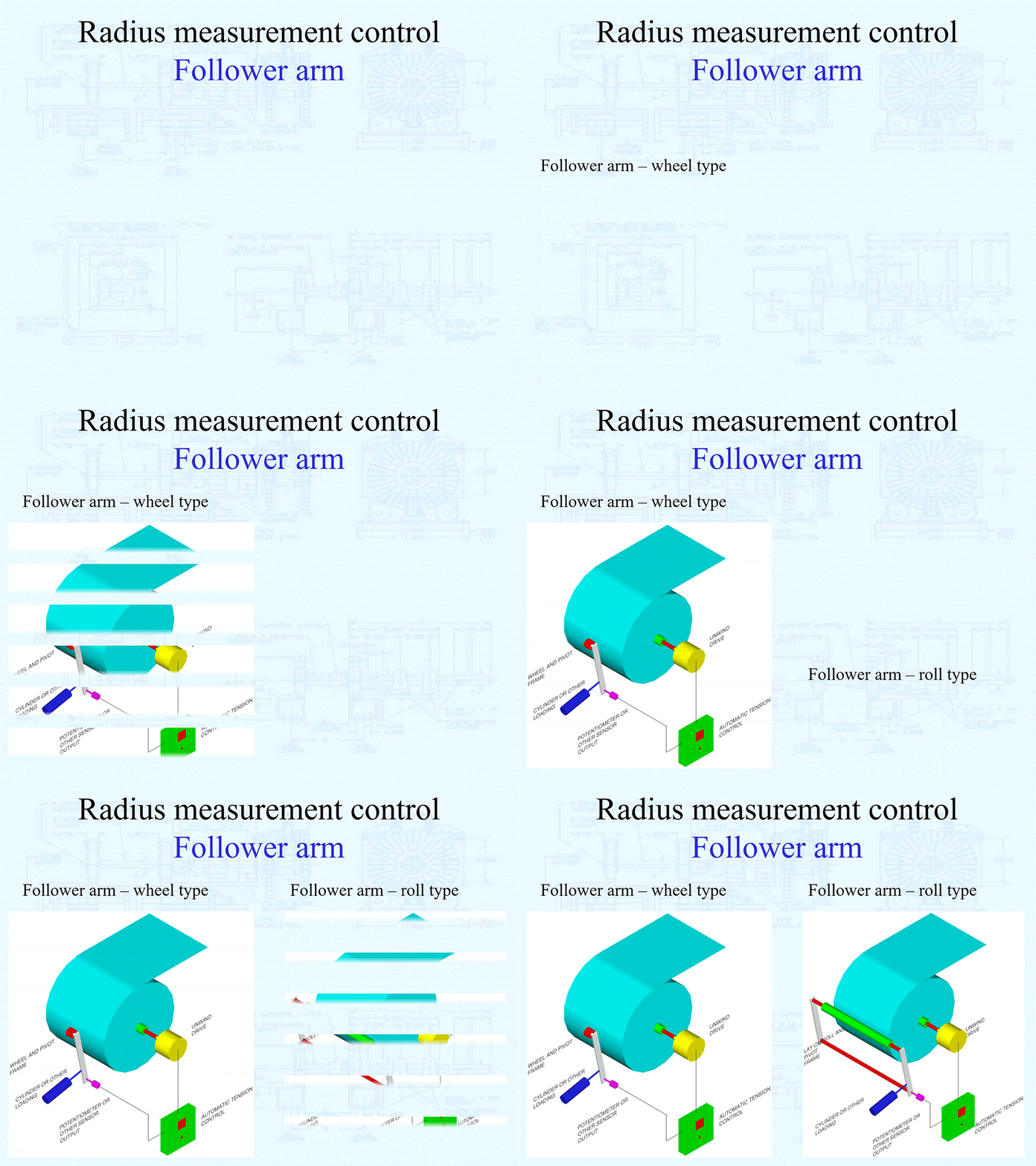
Follower arm or lay-on roll type control is the oldest technology for diameter measurement. This type of control has a wheel or roll, which lays on the unwind or rewind roll outer diameter. The wheel or roll is mounted to a pivoting arm. The pivoting arm is spring or air loaded with a sensing device mounted to the pivot point. The sensing device is usually a potentiometer, but proximity sensors and hall-effect sensors are also common. This sensing device feeds back to the tension control and an output is generated to the drive to control torque proportional to roll build.

No alt text provided for this image

Follower arm tension control advantages:

  • This type of tension control is very simple.
  • Good replacement for operator controlled manual control.
  • Inexpensive.
  • Easy to install.


Follower arm tension control disadvantages:

  • Normally, this control does not have compensation for out of round rolls. Out of round rolls could cause this control to oscillate.
  • The lay-on roll or wheel gets in the way of changing rolls.
  • Major mechanical modifications are necessary to increase unwind or rewind roll capacity.
  • There are a lot of mechanical parts, which will require maintenance.
  • This is an open loop tension control. It does not control tension by measuring tension in the web. It controls tension by measuring roll diameter. It assumes all of the conditions effecting web tension are correct.
  • This type of tension control can only control unwind and rewind zones. It cannot control internal zones.
  • Material must be contacted, which could harm some sensitive materials. 


Diameter measurement control – ultrasound:

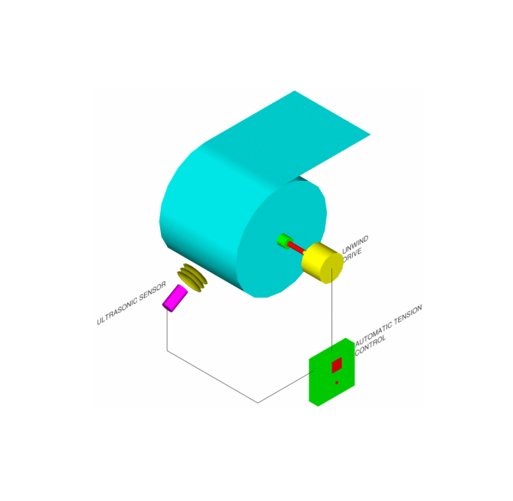
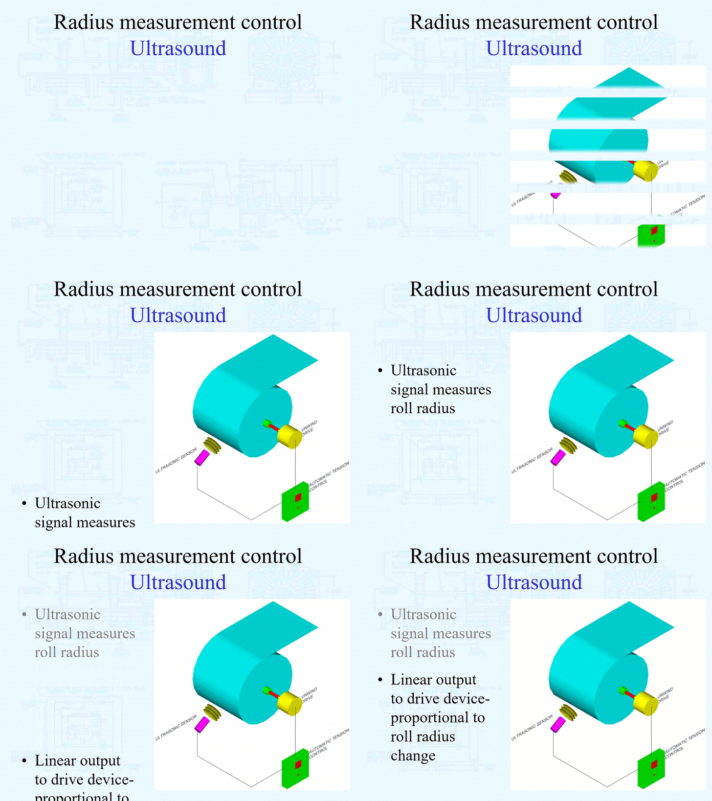
Many advantages over the follower arm type tension control make the ultrasound tension control a more popular choice today. The ultrasonic sensor emits a signal that travels to the rolls surface, bounces off and returns to the sensor. The control logic measures the time it takes for the signal to return to the sensor and in that way measures distance. Since the control measures distance, it will give a linear output relative to the radius of the roll to a drive device. As we discussed earlier, the equation torque = tension x radius is linear, so if the ultrasound tension control gives a linear output relative to radius it will control drive torque through an unwind or rewind roll built to supply constant tension.

No alt text provided for this image

Ultrasound tension control advantages:

  • This type of tension control is very simple.
  • Excellent replacement for operator controlled manual control.
  • Relatively inexpensive.
  • Extremely easy to install.
  • Gives a true linear output relative to roll diameter.
  • Models of this control are available with compensation for out of round rolls to eliminate control oscilation.
  • Ultrasonic sensor can be “tucked” away, out of machine operators way. It can be mounted anywhere around the roll circumference, as long as it get a clear view of roll radius.
  • Modifications to increase unwind or rewind roll capacity is easy. All that is needed is to move the transducer and recalibration.
  • No mechanical parts to wear out.
  • Models are available with limit alarms. Such as low or empty roll.
  • No material contact for sensitive materials.


Ultrasound tension control disadvantages:

  • This is an open loop tension control. It does not control tension by measuring tension in the web. It controls tension by measuring roll diameter. It assumes all of the conditions effecting web tension are correct.
  • This type of tension control can only control unwind and rewind zones. It cannot control internal zones.
  • Any object put between the roll outer diameter and the transducer affects it.
  • Electronic calibration is necessary with initial set up.
  • Some types of material, such as nonwovens, may absorb the ultrasonic signal. If the signal does not return to the sensor, it will not operate.
  • The perpendicular positioning of the sensor relative to rolls centerline is somewhat critical. If the sensor is “knocked” out of position, it may not operate properly.


Diameter measurement control – diameter calculator

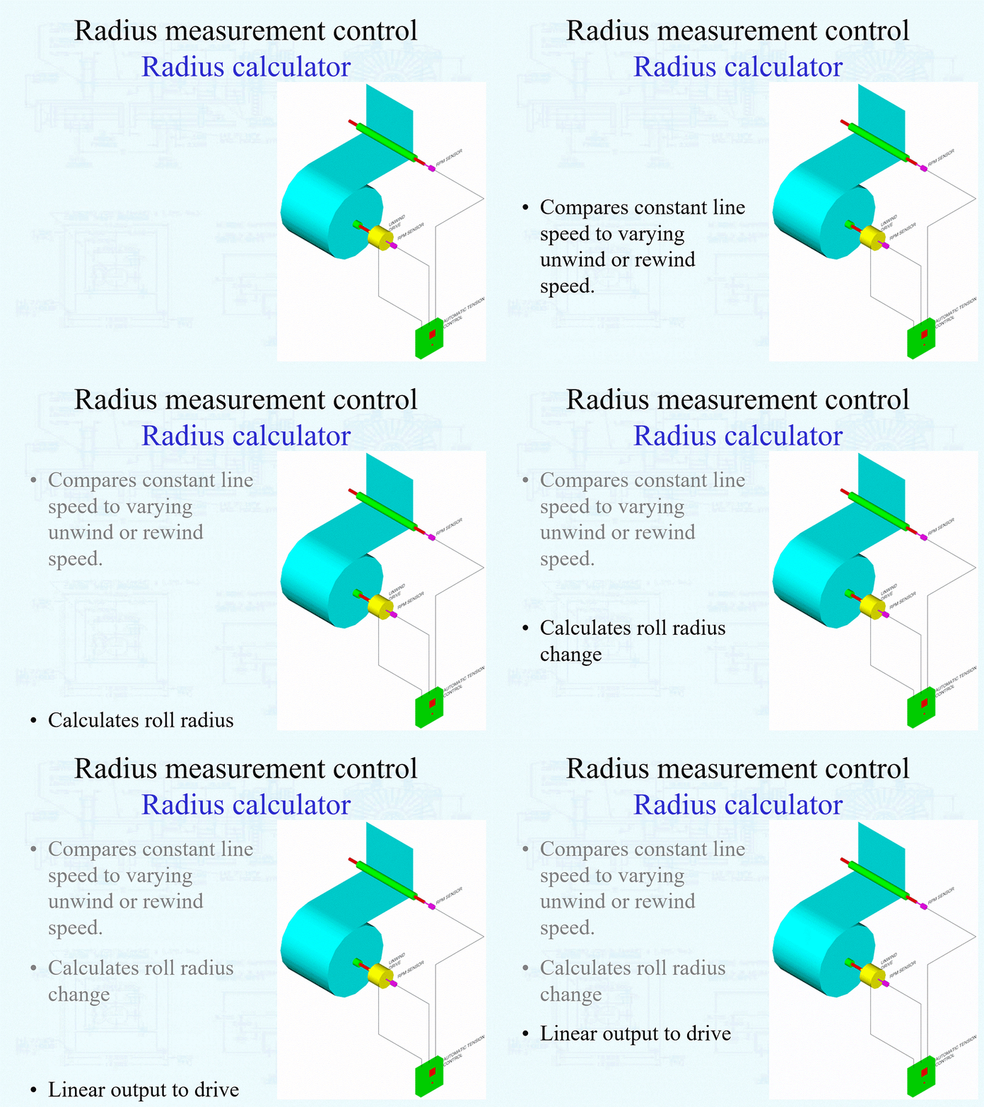
The last type of diameter measurement control we will discuss is the diameter calculator. This type of control uses sensors at the unwind or rewind shaft and an idler or driven roll. Both sensors detect RPM. They can be encoders or tachometer generators.

Machine speed is constant and known. Unwind and rewind roll speeds both vary relative to roll diameter. By comparing the constant known speed to the varying unwind or rewind roll speed, diameter can be calculated.

No alt text provided for this image

Diameter calculator tension control advantages:

  • Excellent replacement for operator controlled manual control.
  • Relatively inexpensive.

 
Written By: Jeff Damour

Why Do Webs Wrinkle?

Why Do Webs Wrinkle?

Definition of the term Spreader Roll

For the purpose of this presentation, spreader rollers are defined as web transport rollers (driven or idle) that cause cross machine direction web movement, as the web is traveling in the machine direction. There are three purposes of cross machine movement; 1) this action will remove wrinkles, 2) this action can separate slit widths, to prevent interleaving, 3) web width can be stretched a predetermined amount.

This presentation will cover each type of Spreader Roll and how they can be utilized in the applications listed above.

Why do webs wrinkle?

To understand why webs wrinkle and why spreader rollers work, it is necessary to understand the most important web handling principal when it comes to wrinkling. This principal states:

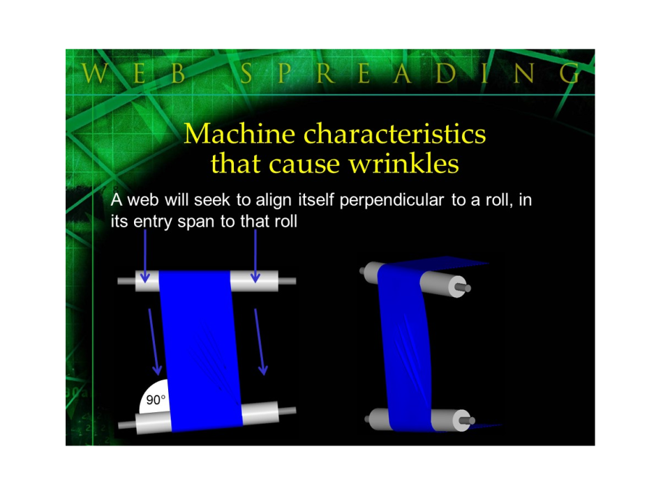
A web will seek to align itself perpendicular to a roll, in its entry span to that roll.

No alt text provided for this image

The web must be in traction with the roll for this web handling principal to be true and effect the web behavior. In other words, if the material slips over the roll face then it can wander or remain in its current alignment with a roll not perpendicular to it.

The reason webs wrinkle can be summed up in one expression – lateral compressive forces. This presentation will seek to explain why lateral compressive forces occur, how to avoid them and spreader rollers that will remove wrinkles when these lateral compressive forces cannot be avoided.

Causes of Web Wrinkles

 In a perfect world, webs would be flat, without gauge band variations. Roll stock would always be wound with the perfect tension from the core through the full roll diameter. Processes would always be run at the perfect tension for each material and operation. All converting processes would be run in humidity-controlled environment, where temperatures never vary. All rollers would be parallel from unwind to rewind and balanced perfectly. There would be no machine vibration. There would be no long, unsupported web lengths. You get the idea.

Unfortunately we do not live and work in a perfect world. One or a combination of any or all of the circumstances listed above will cause wrinkles.

Web characteristics that will cause wrinkles:

  • Gauge band variations (thickness variations) across web width, cross machine direction (figure 1) will cause wrinkles because tensions will vary across the web width. These tension variations will cause tensile stress in the thicker areas and compression in thinner areas. This compression causes wrinkles.
No alt text provided for this image
  • Tight side/loose side. This condition is caused by the web being longer (linearly), on one side than the other, in the machine direction. If you were to lay flat an extremely long length of material in this condition under no tension, it would actually arc instead of being straight. This condition again creates tensile stress on the tight (short) side and compression on the loose (long) side, causing wrinkles.
No alt text provided for this image
  • Baggy center, tight edges. The web being longer in the center than the two edges, in the machine direction, causes this condition. If you were to lay material with this characteristic, flat, then you would see ripples or bubbles develop in the center while the edges were straight and flat. In a converting process, webs with this material characteristic will wrinkle because most of the tension that is typically evenly distributed across the full width is mostly distributed on the shorter (machine direction) edges than longer (machine direction) center. Tensile stress on the edges will create lateral compression in the center of the web, causing wrinkles.
No alt text provided for this image
  • Baggy edges, tight center. The web being longer on the edges than the center, in the machine direction, causes this condition. If you were to lay material with this characteristic, flat, then you would see ripples or bubbles develop on the edges while the center was straight and flat. In a converting process, webs with this material characteristic will wrinkle because most of the tension that is typically evenly distributed across the full width is mostly distributed on the shorter (machine direction) center than longer (machine direction) edges. Tensile stress in the center will create lateral compression on the edges of the web, causing wrinkles.
No alt text provided for this image
  • Poorly wound roll stock (parent roll) will cause wrinkles for the following reasons:
  • Tension too high, especially at the outer layers of the roll can cause inner layers to buckle. This is evident by viewing the end of the roll and observing a starring effect. In extreme cases, the core may even be collapsed. This roll characteristic will cause the web to be wrinkled before it enters a converting process.
  • Tension too low will cause the roll stock to be wound loose. Layers will slip on each other, making tension control ineffective or intermittent. This will cause the material to neck down (under tension) and expand (when tension is low or nonexistent). These compression and decompression forces will create web wrinkles.
No alt text provided for this image

Machine characteristics that will cause wrinkles:

  • Idler roll buckling or deflection will cause wrinkles because the web will actually deflect out of its normal running plane at different intervals across the web width. This out of plane condition will occur wherever the greatest amount of deflection (usually the center) is in the idler roll. When roll deflection occurs, webs will wrinkle because they will compress toward the deflection point.
No alt text provided for this image
  • Air entrainment in webs as they flow over rollers will cause wrinkles. Air entrainment will create slippage between the web and the roll face. If this slippage occurs, then the web is not in traction with the roll. For the web handling principal, that a web will seek to be perpendicular to a roll in the entry span to that roll, to effect web behavior, it must be in traction with the roll. If the web is not in traction with a roll, it can wander or stay aligned with that roll to which it is not perpendicular. Webs that wander will wrinkle because the web will move to be perpendicular to the next roll with which it has traction. This movement to remain perpendicular will cause a strain on the web. Air entrainment problems can be detected by viewing idler rollers that stop rotating during the converting process. Also, if wear spots are seen across idler roll faces, air entrainment is probably the problem. Machinists’ bluing dye can be applied to idler rollers where air entrainment is suspect to detect wear spots.
No alt text provided for this image
  • Material roll buckling or deflection. If the parent roll deflects on its support mechanism (air shaft, mechanical chucks or core cones mounted on a simple steel through shaft) then compressive forces will cause the material roll to buckle and wrinkle before the web enters the converting process.
No alt text provided for this image
  • Varying tension through several different types of processes in one converting line (figure 10) will cause wrinkles. A good example of this is tension through a coating section, printing process, drying section and slitting section. Tension through the coating section may be high, then through the printing process may be lower, then through the drying process lower yet, then through the slitting section may be high again. Wrinkles will occur under these conditions because the web will stretch and contract creating compressive and decompressive forces.
No alt text provided for this image

Lateral (cross machine direction) compressive forces are created in the web because of a high tension. Decompressive forces are created from the web trying to return to its natural state after leaving a high-tension section. These lateral compressive and decompressive forces are very similar to stretching and relaxing a rubber band. When you stretch a rubber band, its length grows and its width narrows (lateral compressive forces make the rubber band narrow). When the same rubber band is relaxed, the length shortens and the width grows as it tries to return to its natural state (lateral decompressive forces). These individual tension sections (zones) can be affected by braked, defective or unbalanced idler or driven rollers that will create tension variations as the web is flowing through the process.

A braked roller, defective roller or a defective bearing in an idler roller, will cause tension to vary on the downstream side of the idler roll. This will vary tension very similar to the situation described above. Again, as tensions vary, the web will stretch and contract creating wrinkles.

  • Other web expansion and contraction effects on the web will create wrinkles. Examples of these effects are heat on plastics and moisture in paper.
  • If idler rollers and/or driven rollers are not parallel to each other, wrinkles will occur. These occurrences are again introduced because of the web handling principal, that a web will seek to align itself perpendicular to a roll in the entry span to that roll. As the web is seeking this right angle it will move or bend out of its normal running plane. This will create tension to variations across the web, tensile stress in high tension area and lateral compression in the low tension area.
No alt text provided for this image

Why use spreader rollers?

To remove wrinkles. As described in the previous section, webs will wrinkle for a lot of reasons. Some times, wrinkles can be avoided by correcting certain errors in converting processes. Many times, wrinkles will reoccur even though it seems all conditions are perfect in the converting process. These reoccurring wrinkles can only be removed with a spreader roll.

No alt text provided for this image

Spreader rollers used to remove wrinkles will do so prior to the wrinkle becoming a crease. If a wrinkle becomes a crease it becomes very difficult or usually impossible to remove. A wrinkle will become a crease when it enters a station where the web is being nipped or rewound.

Typically, spreader rollers are used as a “bandage” for wrinkling problems. Spreader rollers do not permanently change the characteristics of material. Multiple spreader rollers may be required for one converting process, each roll located just prior to each converting operation where wrinkles cause a problem or may become creases.

Applications where accumulated wrinkles require more cross machine movement than one spreader roll can provide will require multiple spreader rollers. Usually, multiple spreader roll applications will incorporate several of the same type of spreader rollers, each immediately following the other, again just prior to each operation where wrinkle removal is required. Different types of spreaders should not be used in close proximity to each other, because each type utilizes different principals of web spreading. Many times, when different types of spreaders are used together, results can become unstable and unpredictable. Some times, different types of spreaders will counter act each other and cause wrinkles, this usually does more harm than good.

Imagine the print quality out of a printing station or edge quality out of a slitting station with an in-running wrinkle or crease. Spreader rollers are used to improve product quality and reduce waste by removing some, most or all of the wrinkles just prior to a converting operation. Bottom line – spreader rollers used to remove wrinkles will increase profits by reducing or eliminating defective product. With the use of spreader rollers, web speeds can often increase and webs that could not be run without wrinkling (example-very thin or soft webs) in the past can now be processed with little or no problems.

To separate slit widths, to prevent interleaving. When a web is slit into several separate widths, each width takes on the properties of a separate web. Each width will have its own tension and each width will have a tendency to wander, similar to how the parent web can wander (this is why the parent web is usually edge guided).

No alt text provided for this image

Normally, several slit widths are wound on a duplex (two station winder). This type of rewind has two separate rewind shafts, each with its own drive. Use of a duplex rewind will prevent interleaving by placing each slit width alternately, on the two separate rewind shafts. Example – The first slit width is placed and rewound on to shaft A, the second slit width is placed and rewound on shaft B, the third slit width is placed and rewound on shaft A, etc. Because each slit width is placed with the space of the next slit width between each rewound roll it is impossible for interleaving to occur.

However, in applications where several slit widths are wound on to a single rewind shaft, edge interleaving will occur with even the slightest wander by each slit width. When this interleaving occurs with several layers of web wraps on the rewind shaft, the edges of each slit roll will become overlapped. It is very difficult or impossible to separate each rewound roll if the edges are overlapped.

Bowed (curved axis) spreader rollers will prevent edge interleaving and roll overlap on a single rewind shaft by evenly separating each slit width. The separation must be greater than the maximum cumulative web wander for each slit width. This separation principal works, based on the web handling principal that the centerline of each slit width (now having the properties of a separate web) will seek to be perpendicular to the intersection point on the arc (curved axis) of the bowed roll.

No alt text provided for this image

To stretch the web across the width. Some applications require that a web be stretched in the cross machine direction. A good example of this is a tenter frame application, often used for textiles. While a tenter frame is not a spreader roll by definition it does stretch material in the cross machine direction. Spreader rollers are used quite often immediately following a tenter frame to keep the web taught, so it doesn’t return to it’s natural width state. Spreader rollers may be used in this application to increase stretch in the cross machine direction.

No alt text provided for this image


 All spreader rollers have the ability (with varying aggressiveness) to stretch a web. Each uses it’s inherent spreading principal to do so which we describe further in the document (see Principals of Operation for each type of spreader).


Written By: Jeff Damour

Nip Type Anti-Wrinkle System for Web Converting

Description:

Nip type spreader rollers are normally short face rollers (less than 12” face) and small diameter (less than 3” diameter). These rollers are supplied in a left and right hand set. Each set consists of 2 rollers pre-loaded so each roller face is pressed together; these roller faces must be parallel with each other. Each roller set is very similar in design to other nip rollers used in converting (such as drive nips). One of the rollers in each set must be rubber covered (for traction); sometimes both rollers in the set are rubber covered.

Theory of operation:

The left and right-side nip sets are mounted to the machine frame and each edge of the web is fed through the nip rollers. The left and right side nip roller sets are then angled away from each other, facing in the downstream direction. Because of the web handling principle, that a web will seek to align itself perpendicular to a roller, in its entry span to that roller, each web edge will seek to be perpendicular to each nip roller set. This type of spreader roller is extremely aggressive and will spread more aggressively than most other types of spreader rollers.

No alt text provided for this image

This type of spreader roller has no wrap angle. Because the web is not supported across its full width, the material must be fed straight in and out of this spreader roller assembly.

Advantages:

  • This type of spreader roller is the most aggressive.
  • Simplicity of design makes this type of spreader roller easy to maintain.
  • The amount of spreading is easily adjustable, by changing the angle of each nip set independently of each other.
  • Works well with woven and non-woven webs.
     
  • No alt text provided for this image


Disadvantages:

  • Because this spreader roller will not support the web across its full width, it will mark, distort and possibly tear most foils.
  • This type of spreader roller is specifically designed for woven and non-woven materials. Any other type of materials may have difficulty with this type of spreader roller, because of web distortion.
No alt text provided for this image
Written By: Jeff Damour

What is Web Tension and Why Do I Care?

What is tension?

No alt text provided for this image

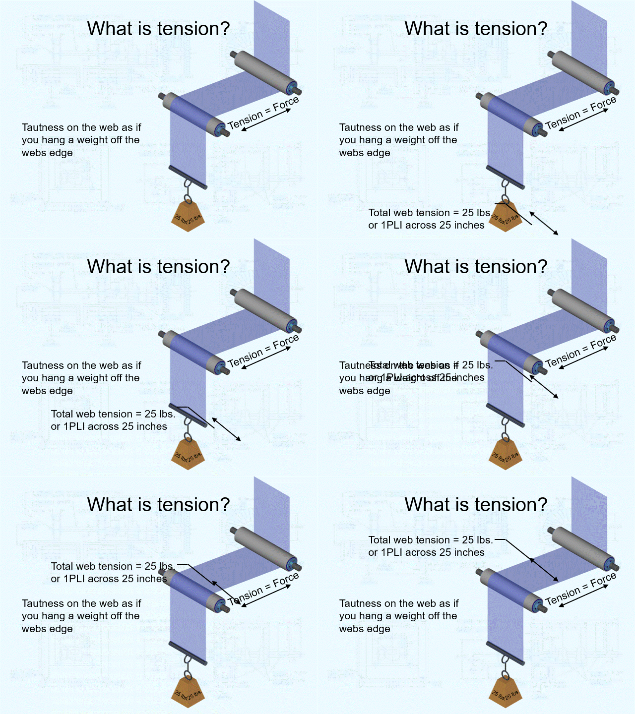
Typically, tension is measured in PLI (Pounds per Linear Inch) in the US. If you know PLI and you want to know total tension applied to the web, multiply PLI times the width of the material in inches. If you know total pounds of tension applied to the web and you want to know PLI, divide the total pounds of tension across the web by the width of the web in inches.

• PLI (Pounds per Linear Inch) = total pounds of tension / web width in inches

• Total pounds of tension = PLI X web width in inches

The tension applied to a web can be described as the webs tautness as if you hung a weight off the edge of the web. The tension on the web would be equal to the weight in pounds. PLI would be equal to the weight in pounds divided by the web width in inches.

No alt text provided for this image

Why is tension important to me?

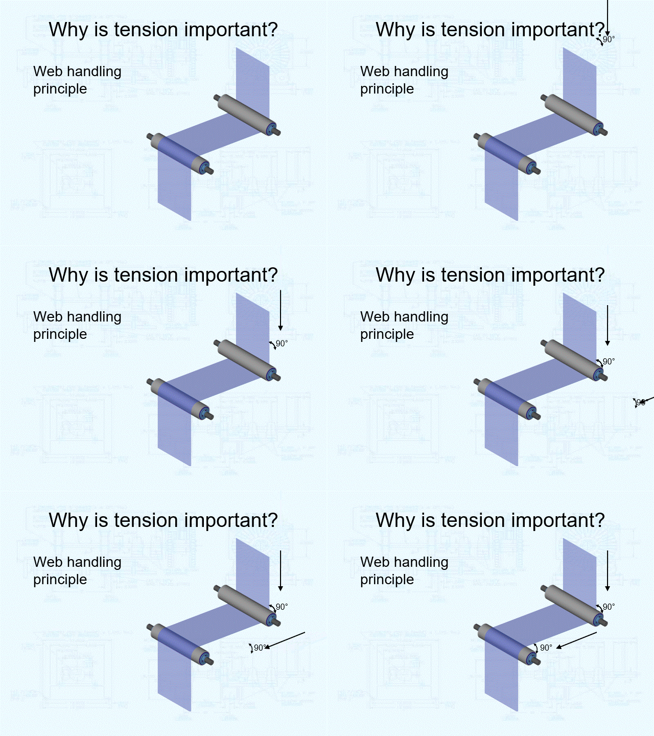
• It is impossible to control your web without proper tension being applied. The web must be “in traction” with all machine idler rolls and driven rolls to ensure proper web handling and control.

• The web handling principal states a web will seek to align itself perpendicular to an idler or driven roll. This web handling principal is applied to route webs through processes with parallel idler rolls and driven rolls. It is applied when web guides are used to steer webs. And it is also applied in many wrinkle removal devices. However, the web handling principal does not apply to webs that are not in traction with idler or driven rolls. In other words if the web slips over the face of an idler or driven roll it can wander from side to side or if the web slips on web guiding idler rolls it will not move where the web guide attempts to steer it. Tension must be applied to webs to keep them in traction with idler and driven rolls.

No alt text provided for this image

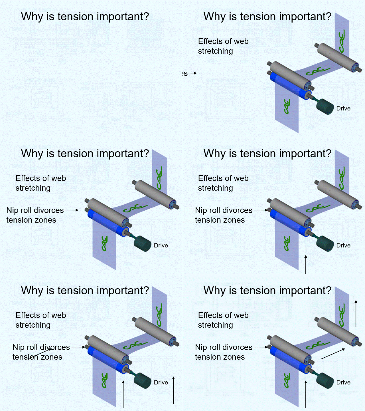
• All webs stretch in the machine direction as tension is applied to them. It is important to apply proper tension to a web so that it can be handled through the machine and processes without over-stretching

No alt text provided for this image

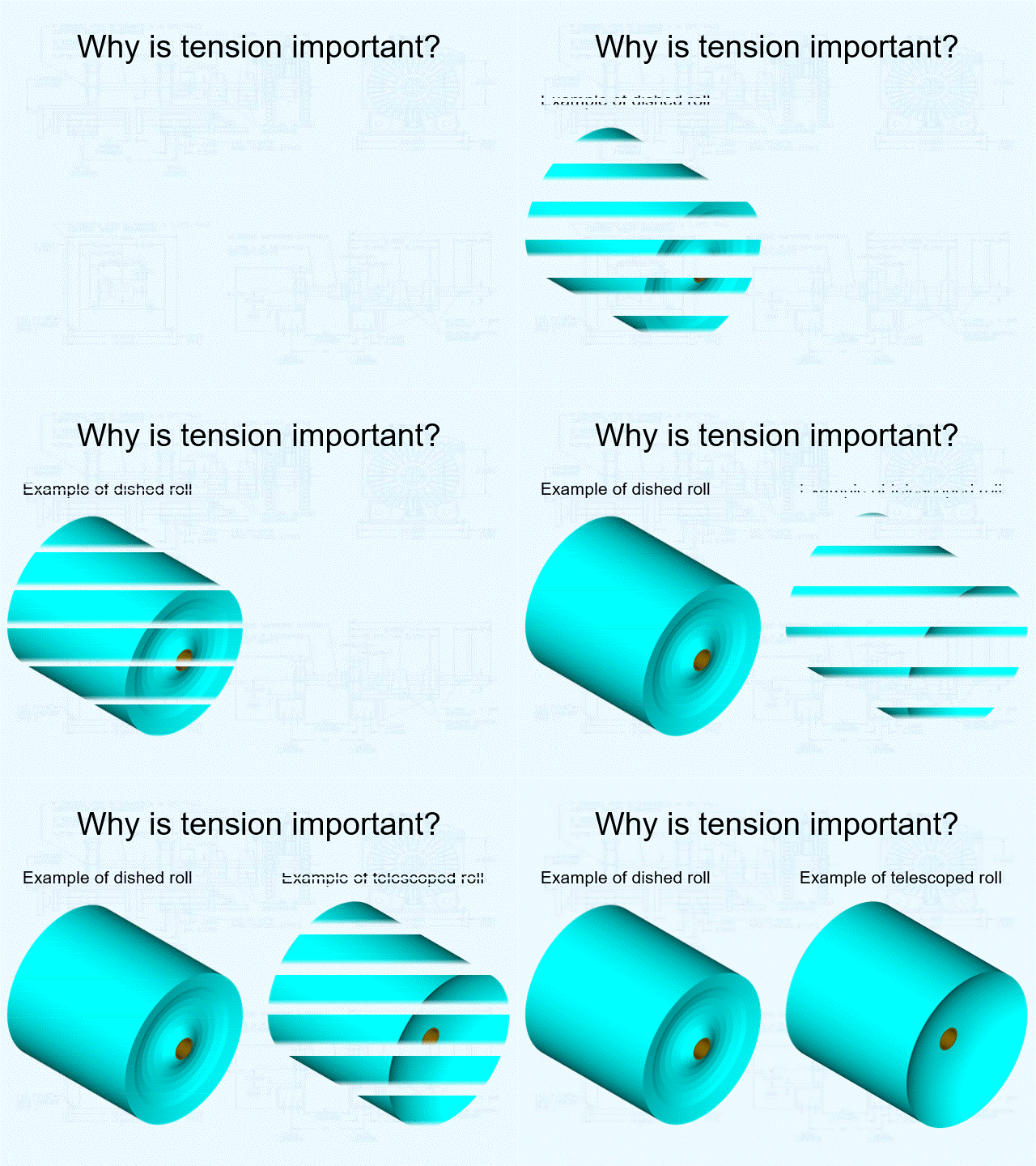
• It is impossible to unwind rolls into a process without proper tension control at the unwind station. Telescoping, “dished” rolls, wrinkles and even web breaks will occur when tension is not controlled at the unwind station.

• It is impossible to rewind rolls from a process without proper tension control at the rewind station. Telescoping, “dished” rolls, wrinkles and even web breaks will occur when tension is not controlled at the rewind station. 

No alt text provided for this image

• Many converting operations require proper registration to print or die cut stations. Proper tension control is essential to controlling print to print or die cut registration.

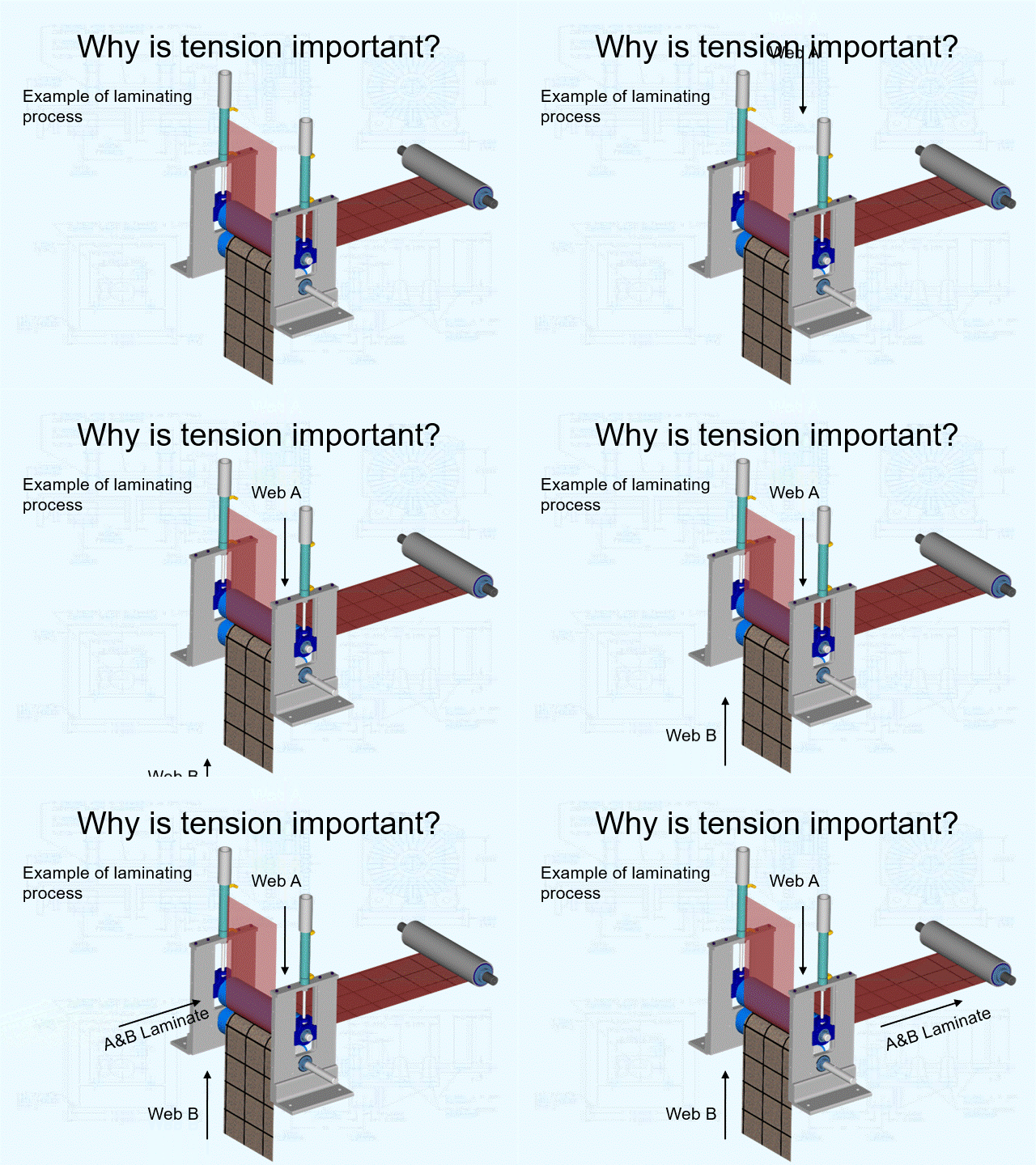
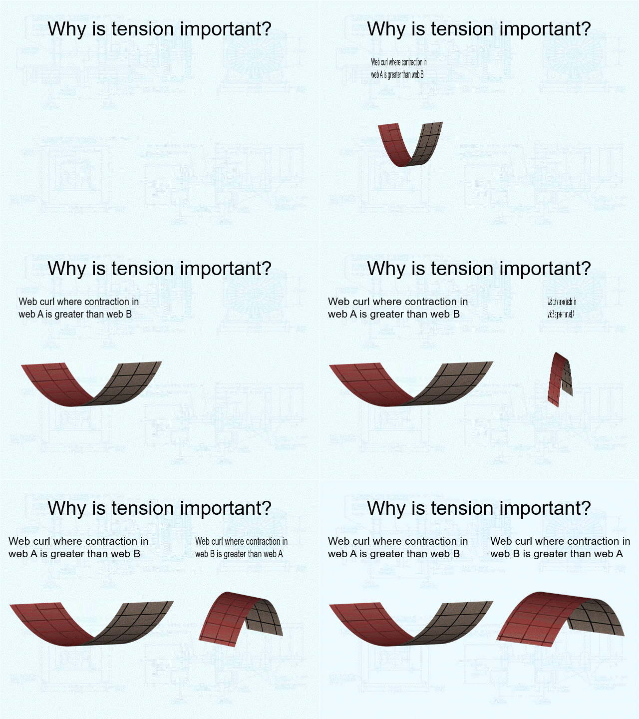
• Laminating operations require layers to be laminated with proper tensions to avoid web curl.

No alt text provided for this image
 
No alt text provided for this image

• Slitting operations require proper slit position, which is a function of tension and web guiding.

• When tension is too high webs will stretch in the machine direction and compress in the cross machine direction. This narrowing of the web width can cause wrinkles to occur.

• When tension is too low webs will shrink in the machine direction and web width will widen in the cross machine direction. This widening of the web width can cause wrinkles to occur. 

Understanding what web tension is, its function in your converting process and why it is important are the first steps to properly controlling web tension to benefit your operation.

Written By: Jeff Damour

New On Shaft Inflation Toggle Valve Air Shaft Makes Roll Changes More Efficient

Converter Accessory Corporation (CAC®) is introducing a patented new inflation toggle valve COR-LOK® air shaft option, toggle valve COR-LOK air shaft, that helps reduce roll changeover times. Toggle valve COR-LOK air shaft employs standard rotary union for pneumatic hook-up and is specifically engineered for use in cantilevered applications. It is available in COR-LOK air shafts in 2 to 18 inch diameters..

According to Jeff Damour, CAC engineering manager, the main advantage of the toggle valve COR-LOK air shaft is that it facilitates rapid roll changeovers. Since the easily reached toggle valve is built into the end of the air shaft, an operator does not have to leave the station to access a remote inflation control or retrieve any tools.

No alt text provided for this image


”The toggle valve COR-LOK air shaft is a simple design that makes an exceptional contribution to efficiency," Damour said. "This option is well designed for use with label presses and is available in stainless steel for washdowns in food grade applications and offers all the advantages of our other COR-LOK air shafts.“

The toggle valve COR-LOK air shaft system is also compatible with CAC's sleeve-based core adapting option that allows converters to run varying core sizes, both 3“ and 6“ for example, on the same shaft or air shaft. This option allows rapid changeovers between rolls with differing core diameters ranging from 3 to 18 inches. CAC's sleeve-based core adapting system is especially effective in label production and other narrow web operations. It offers converters the additional economical option of employing two short sleeves at each end of the shaft rather than a single, longer sleeve to adapt varying core sizes.

No alt text provided for this image


The most recent COR-LOK air shafts and chucks feature a freshly engineered tubing (bladder) design contoured to match the geometry of the company's unique, spiraled shaft body. Compared to previous designs, the economical new contoured tubing allows increased gripping power, a longer tubing life and exceptionally easy replacement. The new COR-LOK air shaft and chuck systems also offer several air valve options intended to match virtually any plant requirements. To fully inflate, they require only 90 to 120 PSI.

COR-LOK tubing is unique in that it can be quickly and easily sized, on site, to match any CAC air shaft or chuck. Tubing lengths can be ordered in advance and stocked, thus minimizing down time, even in plants where a large diversity of air shafts and chuck sizes exists. To facilitate easy changeovers, the tubing is mechanically fixed, rather than vulcanized, to the air valve.

All COR-LOK air shafts and chucks offer exceptional gripping power over the full core length; feature a unique, wear resistant aluminum leaf locking system, and ensure core protection and damage free operation. They are lightweight and carefully designed for easy, safe operation.

CAC hosts an online air shaft support center featured on www.converteraccessory.com offering detailed instruction for servicing air shafts from CAC and other manufacturers. The air shaft support center allows for online ordering of spare parts, including aluminum core cones, tubing, valves and valve cores.

In addition to detailed instruction, online chat is also available, but not required to access information. Currently celebrating its 49th year of success, Converter Accessory Corporation designs, engineers and manufactures web handling equipment for converters of paper, film, foil, nonwovens and textiles. Engineered solutions include high quality, cost effective equipment from the simplest aluminum core cone to the most sophisticated unwind/rewind system. CAC® is represented by knowledgeable sales engineers and provides extensive consultation and post sales support.

Written By: Jeff Damour

How do we select the most effective wrinkle removal solutions?

How do we select the most effective wrinkle removal solutions?

Jeffrey Damour

Jeffrey Damour


Engineering Manager at Converter Accessory Corporation
108 articles 

Most anti-wrinkle rollers remove wrinkles. Concave rollersgrooved rollersnip type spreader rollersbowed rollers and expanding surface rollers all remove wrinkles. They may vary in their aggressiveness and the amount of wrinkles they take out, but they all work to some extent to help with web wrinkle problems.

So how do you select the right one? Well, the question to ask yourself (and your supplier) is what are the rollers doing to my material in the long run? Especially with new directives handed down from your customers to run thinner materials.


Thinner materials wrinkle more because they are less stable than their thicker counter parts, so when you attempt to convert thinner gauge "stuff" you may get wrinkles where you never had them before. Be careful how you select your next anti-wrinkle roll to help solve this problem.


Anti-wrinkle rollers can harm and distort your thin materials (paper, film, foils, non-wovens). Bowed rollers and concave rollers have non-linear faces, which will increase the tension profile of the web in certain areas and decrease it in other areas. This may stretch or distort your webs permanently. Grooved rollers and nip type spreaders have non smooth surfaces which may mark your web or cause different wrinkles.


So while these rollers do remove wrinkles, sometimes the most important question is - What am I doing to my materials by using these rollers? Often times these types of spreaders can cause more harm than good.

Try to find an anti-wrinkle roller with linear face and smooth surface. They aggressively remove wrinkles with zero web distortion and deformation.

Written By: Jeff Damour

How do I measure tension in my existing process?

Where Web Tension Exists, How to Measure Tension and a Word About Taper Tension

Most converting applications include three types of tension zones – unwind, internal and rewind. Each zone must be controlled independently. Multiple zones of each type are common in many converting applications; however, they normally are categorized as unwind, internal or rewind.  

No alt text provided for this image


Each tension zone is very unique and must be controlled independently. Since independent tension controls are used in each zone, each zone may have its own tension level. This means, for example, tension in the unwind zone may be 1 PLI then increase to 2 PLI in the internal zone then decrease to 1.5 PLI in the rewind zone.

Torque required to provide a certain level of tension to a web is total tension measured across the web times roll radius. This means the torque driving the unwind shaft must decrease at a linear ratio, relative to roll diameter, as an unwind roll decreases in size, through a machine run, to keep tension constant. Conversely, the torque driving the rewind shaft must increase at a linear ratio, relative to roll diameter, as a rewind roll increases in size, through a machine run, to keep tension constant. Tension in the unwind and rewind zones is very dynamic. Roll diameters are constantly changing, so torque and speed must be constantly adjusted relative to changing roll diameters. Tension and speed in the internal zones is much more stable since roll diameters in these zones does not change. However, some control is required to set and maintain desired levels. Web defects, splices, desired machine speeds, machine defects and other variables will effect tension in the internal zones.

No alt text provided for this image

Remember the equation of torque = tension x radius is linear, so torque must be decreased (for unwinds) and increased (for rewinds) at a linear rate relative to roll radius. For example, if you start with a 17.5 inch roll radius (35 inch diameter) and unwind down to a 1.75 inch core radius (3.5 inch diameter); 17.5 divided by 1.75 is 10:1 ratio. That means, if you start at 100 inch pounds of torque at the beginning of the unwind roll for proper tension, the torque must be linearly decreased to 10 inch pounds of torque at the core to maintain constant tension.

The machine designer must determine required tension levels for each zone. Often times required tension levels can only be determined after actually running the web through the machine, since all webs and all processes are somewhat unique. TAPPI (Technical association of the Pulp and Paper Industry), as well as many other industry organizations, publish estimated proper tension levels for several different types of webs and laminations. However, keep in mind these values are only guidelines and “best estimates” based on many years of combined industry experience. The actual best tension to run your specific web and process will, most likely, vary from the guideline. Another very general rule of thumb is proper web tension is usually between 10-25% of the tensile strength of your web.

You can measure the tension at which you currently run your process. There are several methods for doing this.


  • If you already have a load cell tension control, it normally has the ability to display actual tension in total pounds across the web. You can also purchase load cells with only a display (no control) if you would like to measure tension within any zone in your machine. 
No alt text provided for this image


  • If your machine has dancers, you can calculate the loading of the dancer on the web if you know the web geometry and the loading force on the dancer. To do this, you will need a drawing of the dancer and web path through the dancer. You also need to know the type of loading and the force applied. Another simpler method would be to place a scale of some sort to measure the force the dancer is loading on the web. Do this without web threaded through the dancer. Remember, as long as the dancer remains somewhere within its travel (between its physical limits of completely full or completely empty) the tension on the web is equal to the loading in the dancer.  
No alt text provided for this image


  •  Another crude but very effective way to measure tension in the unwind zone is the “fish scale method”. This method works for the unwind zone only. It can only be utilized if there is a brake on the unwind station. Unwrap a small amount of material off the unwind roll. Set the unwind brake to the torque output normally set for a machine run. Wrap the leading edge of the web around a bar and hook the “fish scale” through the bar. Pull on the fish scale until the unwind starts to turn. Record the weight reading on the fish scale. This is the actual tension on the web, at this point. Divide the total weight by web width in inches to get PLI (Pounds Per Linear Inch). Do not attempt this method of measuring tension if there is a drive motor on the unwind or for a rewind with a drive motor. Serious injury could result if this method of measuring tension is attempted when there is a drive motor at the unwind or rewind zone.
No alt text provided for this image


  • Tension can also be calculated if you know the model of a brake or clutch, the output level to that brake or clutch at a given roll diameter. By knowing the torque output of the brake or clutch we can plug the values into torque = roll radius x tension and extrapolate the actual tension the brake or clutch is delivering to the web.
No alt text provided for this image

Taper tension:

Everything we have discussed so far is based on constant tension applications. Do not confuse constant tension by varying (or tapering) torque to achieve constant tension as taper tension. Taper tension is NEVER desired for the unwind or internal zones. As a web is unwound and is processed, constant web tension is ALWAYS desired. Taper tension is normally desired in the rewind zone. 

No alt text provided for this image


As a roll is rewound each layer builds up compressive forces which can cause inner layers, toward the core, to buckle. Wrinkling, starring and crushed cores will occur if these compressive forces become to great. Taper tension relieves these compressive forces by actually decreasing web tension as the roll builds. The amount of taper tension is normally measured in percentage of set tension. For example, using the same 3.5 inch core diameter and 35 inch outside roll diameter, if taper tension was set to 50%, the tension will be linearly decreased from 3.5 inch core to 35 inch roll diameter so the tension will be half at the outside of the roll compared to the core.

We will discuss how tension controls work in the next installment.

Written By: Jeff Damour

How Open Loop Tension Controls Work

How Open Loop Tension Controls Work
 

How do open loop tension controls work?

First, a word about the term drive.

In many of the descriptions throughout this presentation I refer to the term “drive”. I am using this term as a purely generic term to describe a mechanical device that delivers torque to a roll of material or driven roll(s) in a converting machine. This device could be a motor, brake or clutch. This presentation is not meant to detail drive mechanisms; instead its intent is to describe the fundamental mechanics of tension control systems.

Manual tension control.

The simplest and least expensive method of tension control is manual. They can be as simple as a potentiometer adjusting the torque output of a drive or magnetic particle brake or clutch or an air regulator adjusting the air pressure and therefore torque output of an air brake or clutch. This control method can be used in all three tension zones. Obviously, it is the least accurate of all types of tension controls because it relies completely on operator “feel” to set the proper tension. There is no feedback from the machine to verify any actual process tension levels. Often times they will have some sort of “meter” on the front of the control to display output as a reference point.

Unwind and rewind tension zones are the most difficult to control manually because of constantly changing diameters and therefore need to be constantly adjusted. 

No alt text provided for this image

Diameter measurement control.

There are several types of diameter measurement controls. Each type has its own method of sensing the unwind and rewind roll diameter. These controls are extremely useful for controlling the tension off an unwind and onto a rewind. However, because they control tension by proportionally decreasing (unwind) or increasing (rewind) torque relative to roll diameter change, they do not work for internal tension zones. These types of tension controls are used strictly at the unwind and rewind tension zones. These controls can be supplied with taper tension for rewind zone applications.

Diameter measurement control – follower arm.

Follower arm or lay-on roll type control is the oldest technology for diameter measurement. This type of control has a wheel or roll, which lays on the unwind or rewind roll outer diameter. The wheel or roll is mounted to a pivoting arm. The pivoting arm is spring or air loaded with a sensing device mounted to the pivot point. The sensing device is usually a potentiometer, but proximity sensors and hall-effect sensors are also common. This sensing device feeds back to the tension control and an output is generated to the drive to control torque proportional to roll build.

No alt text provided for this image

Follower arm tension control advantages:

  • This type of tension control is very simple.
  • Good replacement for operator controlled manual control.
  • Inexpensive.
  • Easy to install.

Follower arm tension control disadvantages:

  • Normally, this control does not have compensation for out of round rolls. Out of round rolls could cause this control to oscillate.
  • The lay-on roll or wheel gets in the way of changing rolls.
  • Major mechanical modifications are necessary to increase unwind or rewind roll capacity.
  • There are a lot of mechanical parts, which will require maintenance.
  • This is an open loop tension control. It does not control tension by measuring tension in the web. It controls tension by measuring roll diameter. It assumes all of the conditions effecting web tension are correct.
  • This type of tension control can only control unwind and rewind zones. It cannot control internal zones.
  • Material must be contacted, which could harm some sensitive materials. 

Diameter measurement control – ultrasound:

Many advantages over the follower arm type tension control make the ultrasound tension control a more popular choice today. The ultrasonic sensor emits a signal that travels to the rolls surface, bounces off and returns to the sensor. The control logic measures the time it takes for the signal to return to the sensor and in that way measures distance. Since the control measures distance, it will give a linear output relative to the radius of the roll to a drive device. As we discussed earlier, the equation torque = tension x radius is linear, so if the ultrasound tension control gives a linear output relative to radius it will control drive torque through an unwind or rewind roll built to supply constant tension.

No alt text provided for this image

Ultrasound tension control advantages:

  • This type of tension control is very simple.
  • Excellent replacement for operator controlled manual control.
  • Relatively inexpensive.
  • Extremely easy to install.
  • Gives a true linear output relative to roll diameter.
  • Models of this control are available with compensation for out of round rolls to eliminate control oscilation.
  • Ultrasonic sensor can be “tucked” away, out of machine operators way. It can be mounted anywhere around the roll circumference, as long as it get a clear view of roll radius.
  • Modifications to increase unwind or rewind roll capacity is easy. All that is needed is to move the transducer and recalibration.
  • No mechanical parts to wear out.
  • Models are available with limit alarms. Such as low or empty roll.
  • No material contact for sensitive materials.

Ultrasound tension control disadvantages:

  • This is an open loop tension control. It does not control tension by measuring tension in the web. It controls tension by measuring roll diameter. It assumes all of the conditions effecting web tension are correct.
  • This type of tension control can only control unwind and rewind zones. It cannot control internal zones.
  • Any object put between the roll outer diameter and the transducer affects it.
  • Electronic calibration is necessary with initial set up.
  • Some types of material, such as nonwovens, may absorb the ultrasonic signal. If the signal does not return to the sensor, it will not operate.
  • The perpendicular positioning of the sensor relative to rolls centerline is somewhat critical. If the sensor is “knocked” out of position, it may not operate properly.

Diameter measurement control – diameter calculator

The last type of diameter measurement control we will discuss is the diameter calculator. This type of control uses sensors at the unwind or rewind shaft and an idler or driven roll. Both sensors detect RPM. They can be encoders or tachometer generators.

Machine speed is constant and known. Unwind and rewind roll speeds both vary relative to roll diameter. By comparing the constant known speed to the varying unwind or rewind roll speed, diameter can be calculated.

No alt text provided for this image

Diameter calculator tension control advantages:

  • Excellent replacement for operator controlled manual control.
  • Relatively inexpensive.
  • Relatively easy to install.
  • Gives a true linear output relative to roll diameter.
  • Nothing in the way of roll loading or unloading
  • Modifications to increase unwind or rewind roll capacity is easy. All that is needed is recalibration.
  • No mechanical parts to wear out.
  • Models are available with limit alarms. Such as low or empty roll.
  • No material contact for sensitive materials.

Diameter calculator tension control disadvantages:

  • This is an open loop tension control.
  • It does not control tension by measuring tension in the web. It controls tension by measuring roll diameter. It assumes all of the conditions effecting web tension are correct.
  • This type of tension control can only control unwind and rewind zones. It cannot control internal zones.
  • Control logic is somewhat complex (compared to ultrasonic or follower arm type). 9 Electronic calibration is necessary with initial set up. 


Written By: Jeff Damour

How Closed Loop Tension Controls Work


Tension measurement control

There are two types of tension measurement tension controls – dancer roll and load cell types. These controls are “closed loop”. They control tension based on tension in the web. They will compensate for tension changes due to roll diameter change on an unwind and rewind. They will also compensate for tension changes due to splices, bearings, mechanical losses and any of forces acting on the web in the machine direction.

Because these tension controls are “closed loop” and control drives based on actual web tension, they can be used to control the unwind, internal and rewind tension zones. Unfortunately, these controls can not sense roll diameter without external inputs, so by themselves they can not supply taper tension to rewind zone applications.

No alt text provided for this image

Tension measurement control - dancer

There are many different designs of dancer roll tension controls. However, all dancers operate with a common principle. They all incorporate idler rolls that are “loaded” in one direction, while the web tends to move them in the opposite direction. A sensor detects the position of the dancer and tells the drive to increase or decrease in speed or torque to add or remove material from the dancer. As long as the dancer roll remains between its physical limits (completely empty or completely full) tension is constant on the web.

Some of the most common types of dancer roll designs are pivot arm, linear and rotational. One advantage to using dancer roll tension controls that is consistent among all designs is they all have some amount (some designs more than others) of web storage. In other words, dancers actually accumulate a certain length of web in the machine direction. That means they can be designed to be mechanically stable through large roll build ratios (at the unwind and rewind) and will absorb tension fluctuations due to splices, defective bearings or other factors. Dancers not only control torque and/or speed to keep tension constant, they also absorb tension fluctuations, so web tension down stream of the dancer is kept smooth.

No alt text provided for this image

Pivot arm type dancer roll tension controls advantages:

  • This design of dancer is one of the simplest.
  • Most common design of dancer roll tension control.
  • Least expensive dancer design.
  • Can be designed with a large or small amount of web storage, but takes up a lot of space.

Pivot arm type dancer roll tension control disadvantages:

  • Gravity must be taken into account during design.
  • Unit can be bulky and difficult to fit into an existing process.
  • Momentum and inertia is a concern.
No alt text provided for this image

Linear type dancer roll tension controls advantages:

  • This design is compact.
  • Large amounts of web storage are available. Especially with multiple web passes. Excellent design for accumulation needs, to allow splices on the fly.
  • Small package can be easy to install in existing equipment.

Linear type dancer roll tension control disadvantages:

  • Gravity must be taken into account during design.
  • Can be a very complex design.
  • One of the most expensive designs. Rodless cylinders and linear transducers are very expensive.
  • Momentum and inertia is a concern.
  • Rodless cylinders are not available in a low friction model.
No alt text provided for this image

Rotational type dancer roll tension controls advantages:

  • This type of dancer roll design is not effected by gravity. It’s dancer rollers are counterbalanced with each other.
  • Momentum and inertia is greatly decreased with the “push/pull” motion.
  • Generous web storage in a small package.
 

Rotational type dancer roll tension controls advantages:

  • This design can be expensive.
  • This dancer roll design is somewhat complex.
  • Web storage amount is fixed and determined by design. Increasing web storage is a new design.

Friction, gravity, momentum and inertia are all “enemies” of dancer rolls. These factors must be accounted for when designing dancer roll tension controls.

  • Frictional losses greatly affect the accuracy of dancer roll tension controls. Low friction cylinders, such as glass lined or rolling diaphragm cylinders, should be used. Stay away from standard o-ring type cylinders or any type of cylinder with a high breakaway force.
  • Momentum and inertia affect stability and accuracy of dancers. Remember a body in motion wants to stay in motion, so dancers will want to keep moving in the direction they are headed. This could cause the dancer to be unstable and tension spikes. Design dancers as lightweight as possible and avoid weight loading of dancers this will greatly reduce momentum and inertia problems.
  • Gravity affects dancer accuracy. The weight of the dancer must be overcome by the web tension order for the dancer to operate. This weight of the dancer is in addition to the loading on the dancer when considering total web tension delivered to the web. Design dancers so gravity least affects them. Rotational type dancers are not prone to gravity problems because the dancer rollers counterbalance each other. Instead of designing a pivoting or linear dancer to move perpendicular to the floor, design it to move parallel to the floor. This will greatly reduce gravity problems.
No alt text provided for this image

There are many methods of loading dancer roll tension controls. Older units may be loaded with weights. If you need more or less tension you add or subtract weight. Newer dancer roll tension controls may use air cylinders for loading with pressure regulator valves. If you want more or less tension your turn the valve to allow more or less air pressure into an air cylinder. Today dancers are manufactured with electric to pneumatic converters loading low friction cylinders, such as glass lined or rolling diaphragm types. Electric to pneumatic converters are electronic circuits, which receive a signal voltage and output a proportional air pressure. The actual air pressure output is sensed with a pressure transducer and controlled with an electronic pressure regulator. This closed loop sensing circuit allows for very accurate dancer roll loading.

Older dancer position sensors are normally potentiometers. The problem associated with using a potentiometer to sense dancer position is that you have mechanical parts within the potentiometer (wiper against a resistance coil) that constantly wear against each other. This type of sensor may loose accuracy over time and may need periodic replacement. Newer dancer position sensors can be digital potentiometers, encoders or proximity sensors with analog output. These types of sensors do not have mechanically wearing parts, so their accuracy is not affected over time and the need for replacement is rare. 

Tension measurement control – load cell

Load cell tension controls utilize strain gauges and other weight measuring devices to measure the “weight” applied to an idler roll due to tension. The force exerted to the idler roll due to tension in the material is proportional to wrap angle around the roll. The example below shows 180° wrap. However, load cell tension controls work with any amount of wrap angle up to 180°. Wrap angles around the idler rolls utilizing load cells must not vary through roll diameter, that is why these controls use lead-in and lead-out idler rolls.

The machine operator sets the desired tension. Normally measurement signals are generated on both sides of the idler roll and fed into the control unit. The control accepts both signals and processes them together. Process values and set values are compared and an output is generated and sent to the drive to keep tension constant.

No alt text provided for this image

Load cell tension controls advantages:

  • Excellent, accurate tension control at the unwind, rewind and internal zones.
  • Many makes and models to choose from.
  • Very accepted though out the industry for tension control.
  • “High tech” controls are available with IO for PLC interface and data acquisition.
  • Auto-tune units are available to eliminate manual calibration.
  • Inexpensive, simple units are available.
  • Very easy to install at any idler roll location.
  • Minimal machine modifications are necessary to utilize this control.

Load cell tension control disadvantages:

  • No mechanical web storage for web tension fluctuations.
  • Web tension can be unstable. Especially in unwind and rewind zone control with large roll build ratios

It can be difficult to properly design both dancer roll and load cell tension controls to have 100% “authority” over an unwind or rewind drive. Large roll build ratios, very high and low speeds and elastic webs can make both types of closed loop controls very unstable. Combination open loop / closed loop controls are available to help with this problem.

Open loop controls are very stable because they are designed to measure distance (roll build). Unfortunately, open loop controls lack accuracy because they do not know what the tension actually is in the web.

Closed loop controls are very accurate because they actually measure tension in the web and control a drive to keep tension constant relative to a set point. Unfortunately, closed loop control can lack stability when controlling unwind and rewind tension zones because they do not know distance (roll build) and have to control large ratios in a relative small span.

Combination controls utilize both open loop and closed loop technology for unwind and rewind zones. The open loop control in the system normally controls 90% of the output to the drive and the closed loop control “trims” that output 10%. This makes unwind and rewind zone control very stable and very accurate. Theses controls utilize roll diameter information, so taper tension for rewind applications is available.

No alt text provided for this image

Combination closed loop / open loop tension control advantages:

  • Very accurate, very stable tension control for very demanding applications.
  • “High-tech” controls are available with IO and PLC interface.

Combination closed loop / open loop tension control disadvantages:

  • High cost of two tension controls.
  • Mechanically and electronically complex.

When tension controls are applied properly, they will decrease waste due to web defects. They will allow operators to concentrate their efforts in other critical areas of your process. Tension controls can allow you to run your process faster. They can even allow you to run different webs and processes through your machine. Tension controls are essential to increasing your profits.

Written By: Jeff Damour

Why Do Webs Wrinkle?

Jeffrey Damour

Jeffrey Damour


Engineering Manager at Converter Accessory Corporation
123 articles

Definition of the term Spreader Roll

For the purpose of this presentation, spreader rollers are defined as web transport rollers (driven or idle) that cause cross machine direction web movement, as the web is traveling in the machine direction. There are three purposes of cross machine movement; 1) this action will remove wrinkles, 2) this action can separate slit widths, to prevent interleaving, 3) web width can be stretched a predetermined amount.

This presentation will cover each type of Spreader Roll and how they can be utilized in the applications listed above.

Why do webs wrinkle?

To understand why webs wrinkle and why spreader rollers work, it is necessary to understand the most important web handling principal when it comes to wrinkling. This principal states:

A web will seek to align itself perpendicular to a roll, in its entry span to that roll.

No alt text provided for this image

The web must be in traction with the roll for this web handling principal to be true and effect the web behavior. In other words, if the material slips over the roll face then it can wander or remain in its current alignment with a roll not perpendicular to it.

The reason webs wrinkle can be summed up in one expression – lateral compressive forces. This presentation will seek to explain why lateral compressive forces occur, how to avoid them and spreader rollers that will remove wrinkles when these lateral compressive forces cannot be avoided.

Causes of Web Wrinkles

In a perfect world, webs would be flat, without gauge band variations. Roll stock would always be wound with the perfect tension from the core through the full roll diameter. Processes would always be run at the perfect tension for each material and operation. All converting processes would be run in humidity-controlled environment, where temperatures never vary. All rollers would be parallel from unwind to rewind and balanced perfectly. There would be no machine vibration. There would be no long, unsupported web lengths. You get the idea.

Unfortunately we do not live and work in a perfect world. One or a combination of any or all of the circumstances listed above will cause wrinkles.

Web characteristics that will cause wrinkles:


  • Gauge band variations (thickness variations) across web width, cross machine direction (figure 1) will cause wrinkles because tensions will vary across the web width. These tension variations will cause tensile stress in the thicker areas and compression in thinner areas. This compression causes wrinkles.
No alt text provided for this image


  • Tight side/loose side. This condition is caused by the web being longer (linearly), on one side than the other, in the machine direction. If you were to lay flat an extremely long length of material in this condition under no tension, it would actually arc instead of being straight. This condition again creates tensile stress on the tight (short) side and compression on the loose (long) side, causing wrinkles.
No alt text provided for this image


  • Baggy center, tight edges. The web being longer in the center than the two edges, in the machine direction, causes this condition. If you were to lay material with this characteristic, flat, then you would see ripples or bubbles develop in the center while the edges were straight and flat. In a converting process, webs with this material characteristic will wrinkle because most of the tension that is typically evenly distributed across the full width is mostly distributed on the shorter (machine direction) edges than longer (machine direction) center. Tensile stress on the edges will create lateral compression in the center of the web, causing wrinkles.
No alt text provided for this image


  • Baggy edges, tight center. The web being longer on the edges than the center, in the machine direction, causes this condition. If you were to lay material with this characteristic, flat, then you would see ripples or bubbles develop on the edges while the center was straight and flat. In a converting process, webs with this material characteristic will wrinkle because most of the tension that is typically evenly distributed across the full width is mostly distributed on the shorter (machine direction) center than longer (machine direction) edges. Tensile stress in the center will create lateral compression on the edges of the web, causing wrinkles.
No alt text provided for this image


  • Poorly wound roll stock (parent roll) will cause wrinkles for the following reasons:
  • Tension too high, especially at the outer layers of the roll can cause inner layers to buckle. This is evident by viewing the end of the roll and observing a starring effect. In extreme cases, the core may even be collapsed. This roll characteristic will cause the web to be wrinkled before it enters a converting process.
  • Tension too low will cause the roll stock to be wound loose. Layers will slip on each other, making tension control ineffective or intermittent. This will cause the material to neck down (under tension) and expand (when tension is low or nonexistent). These compression and decompression forces will create web wrinkles.
No alt text provided for this image

Machine characteristics that will cause wrinkles:


  • Idler roll buckling or deflection will cause wrinkles because the web will actually deflect out of its normal running plane at different intervals across the web width. This out of plane condition will occur wherever the greatest amount of deflection (usually the center) is in the idler roll. When roll deflection occurs, webs will wrinkle because they will compress toward the deflection point.
No alt text provided for this image


  • Air entrainment in webs as they flow over rollers will cause wrinkles. Air entrainment will create slippage between the web and the roll face. If this slippage occurs, then the web is not in traction with the roll. For the web handling principal, that a web will seek to be perpendicular to a roll in the entry span to that roll, to effect web behavior, it must be in traction with the roll. If the web is not in traction with a roll, it can wander or stay aligned with that roll to which it is not perpendicular. Webs that wander will wrinkle because the web will move to be perpendicular to the next roll with which it has traction. This movement to remain perpendicular will cause a strain on the web. Air entrainment problems can be detected by viewing idler rollers that stop rotating during the converting process. Also, if wear spots are seen across idler roll faces, air entrainment is probably the problem. Machinists’ bluing dye can be applied to idler rollers where air entrainment is suspect to detect wear spots.
No alt text provided for this image


  • Material roll buckling or deflection. If the parent roll deflects on its support mechanism (air shaft, mechanical chucks or core cones mounted on a simple steel through shaft) then compressive forces will cause the material roll to buckle and wrinkle before the web enters the converting process.
No alt text provided for this image


  • Varying tension through several different types of processes in one converting line (figure 10) will cause wrinkles. A good example of this is tension through a coating section, printing process, drying section and slitting section. Tension through the coating section may be high, then through the printing process may be lower, then through the drying process lower yet, then through the slitting section may be high again. Wrinkles will occur under these conditions because the web will stretch and contract creating compressive and decompressive forces.
No alt text provided for this image

Lateral (cross machine direction) compressive forces are created in the web because of a high tension. Decompressive forces are created from the web trying to return to its natural state after leaving a high-tension section. These lateral compressive and decompressive forces are very similar to stretching and relaxing a rubber band. When you stretch a rubber band, its length grows and its width narrows (lateral compressive forces make the rubber band narrow). When the same rubber band is relaxed, the length shortens and the width grows as it tries to return to its natural state (lateral decompressive forces). These individual tension sections (zones) can be affected by braked, defective or unbalanced idler or driven rollers that will create tension variations as the web is flowing through the process.

A braked roller, defective roller or a defective bearing in an idler roller, will cause tension to vary on the downstream side of the idler roll. This will vary tension very similar to the situation described above. Again, as tensions vary, the web will stretch and contract creating wrinkles.


  • Other web expansion and contraction effects on the web will create wrinkles. Examples of these effects are heat on plastics and moisture in paper.
  • If idler rollers and/or driven rollers are not parallel to each other, wrinkles will occur. These occurrences are again introduced because of the web handling principal, that a web will seek to align itself perpendicular to a roll in the entry span to that roll. As the web is seeking this right angle it will move or bend out of its normal running plane. This will create tension to variations across the web, tensile stress in high tension area and lateral compression in the low tension area.
No alt text provided for this image

Why use spreader rollers?

To remove wrinkles. As described in the previous section, webs will wrinkle for a lot of reasons. Some times, wrinkles can be avoided by correcting certain errors in converting processes. Many times, wrinkles will reoccur even though it seems all conditions are perfect in the converting process. These reoccurring wrinkles can only be removed with a spreader roll.

No alt text provided for this image

Spreader rollers used to remove wrinkles will do so prior to the wrinkle becoming a crease. If a wrinkle becomes a crease it becomes very difficult or usually impossible to remove. A wrinkle will become a crease when it enters a station where the web is being nipped or rewound.

Typically, spreader rollers are used as a “bandage” for wrinkling problems. Spreader rollers do not permanently change the characteristics of material. Multiple spreader rollers may be required for one converting process, each roll located just prior to each converting operation where wrinkles cause a problem or may become creases.

Applications where accumulated wrinkles require more cross machine movement than one spreader roll can provide will require multiple spreader rollers. Usually, multiple spreader roll applications will incorporate several of the same type of spreader rollers, each immediately following the other, again just prior to each operation where wrinkle removal is required. Different types of spreaders should not be used in close proximity to each other, because each type utilizes different principals of web spreading. Many times, when different types of spreaders are used together, results can become unstable and unpredictable. Some times, different types of spreaders will counter act each other and cause wrinkles, this usually does more harm than good.

Imagine the print quality out of a printing station or edge quality out of a slitting station with an in-running wrinkle or crease. Spreader rollers are used to improve product quality and reduce waste by removing some, most or all of the wrinkles just prior to a converting operation. Bottom line – spreader rollers used to remove wrinkles will increase profits by reducing or eliminating defective product. With the use of spreader rollers, web speeds can often increase and webs that could not be run without wrinkling (example-very thin or soft webs) in the past can now be processed with little or no problems.

To separate slit widths, to prevent interleaving. When a web is slit into several separate widths, each width takes on the properties of a separate web. Each width will have its own tension and each width will have a tendency to wander, similar to how the parent web can wander (this is why the parent web is usually edge guided).

No alt text provided for this image

Normally, several slit widths are wound on a duplex (two station winder). This type of rewind has two separate rewind shafts, each with its own drive. Use of a duplex rewind will prevent interleaving by placing each slit width alternately, on the two separate rewind shafts. Example – The first slit width is placed and rewound on to shaft A, the second slit width is placed and rewound on shaft B, the third slit width is placed and rewound on shaft A, etc. Because each slit width is placed with the space of the next slit width between each rewound roll it is impossible for interleaving to occur.

However, in applications where several slit widths are wound on to a single rewind shaft, edge interleaving will occur with even the slightest wander by each slit width. When this interleaving occurs with several layers of web wraps on the rewind shaft, the edges of each slit roll will become overlapped. It is very difficult or impossible to separate each rewound roll if the edges are overlapped.

Bowed (curved axis) spreader rollers will prevent edge interleaving and roll overlap on a single rewind shaft by evenly separating each slit width. The separation must be greater than the maximum cumulative web wander for each slit width. This separation principal works, based on the web handling principal that the centerline of each slit width (now having the properties of a separate web) will seek to be perpendicular to the intersection point on the arc (curved axis) of the bowed roll.

No alt text provided for this image

To stretch the web across the width. Some applications require that a web be stretched in the cross machine direction. A good example of this is a tenter frame application, often used for textiles. While a tenter frame is not a spreader roll by definition it does stretch material in the cross machine direction. Spreader rollers are used quite often immediately following a tenter frame to keep the web taught, so it doesn’t return to it’s natural width state. Spreader rollers may be used in this application to increase stretch in the cross machine direction.

No alt text provided for this image


All spreader rollers have the ability (with varying aggressiveness) to stretch a web. Each uses it’s inherent spreading principal to do so which we describe further in the document (see Principals of Operation for each type of spreader).

We will discuss crowned and concave rollers in the next installment of this news letter.


Grooved Rollers for Wrinkle Removal

Grooved Rollers for Wrinkle Removal

Jeffrey Damour

Jeffrey Damour


Engineering Manager at Converter Accessory Corporation

Description:

A grooved spreader roller can be manufactured from a variety of materials, such as steel, aluminum, stainless steel, plated aluminum or steel and hard rubber. A rigid grooved spreader roller has grooves machined into the roller face surface. These grooves (resembling screw threads) are machined – starting from the center of the roller and leading out to each edge of the roller face. The grooves can be supplied in almost any fashion; from as simple as wrapping masking tape across the face of a standard idler roller to a machined groove that has very intricate machining details. Groove design is completely application dependent, however it can be generally stated that the greater the number of groove starts there are the greater the spreading will be realized.

No alt text provided for this image

Theory of operation:

Quite simply the theory is that the grooves will push wrinkles out of the web, from the center out to each edge, which, unfortunately is not always the case (see advantages and disadvantages, below).

No alt text provided for this image

Recommended wrap angle for this type of spreader roller normally ranges between 90° - 180°.

Advantages when applied as an idler roller:


  • This type of spreader roller will remove air when air entrainment is a problem (this in itself will help to remove or prevent wrinkles).
  • Depending on the groove design, these rollers can often be manufactured by most machine shops, rubber roller manufacturer or idler roller supplier. Making this type of spreader one of the least expensive, most readily available types of spreader roller.
  • Simplicity of design, with no special parts, makes this spreader roller extremely easy to maintain.
  • Because this roller is linear across its face, it will not stretch, distort or tear any portion of the web.
  • This type of spreader roller is best suited for use with textiles and non-wovens. It has limited application with papers, foils and films.
No alt text provided for this image

Disadvantages when applied as an idler roller:


  • When this spreader is applied as an idler roller (driven at the surface speed of the web), the grooves do not push wrinkles out from the center of the roller face (even though this is most often believed to be the case). When the surface of the grooved roller is driven at the same speed as the surface of the web (such is the case when used as an idler roller) the tangent point, at any given point across the web or roller face, where the web first touches the roller remains in a constant position through the roller rotation. Because the tangent point of the web lying on top of the groove does not vary, the groove has no cross machine direction movement effect on the web. The belief that the grooves have some effect on the web is mostly an optical illusion (like the illusion caused by a rotating barber shop pole). An engineer once told me an excellent analogy of the non-effect of the grooves on the web in this application (I can’t take credit for the analogy); if you place a plow in a field, does the field plow itself by the rotation of the earth? Of course not, and the reason is because the tangent point of the plow in the field remains constant with the earth in its rotation.
  • This type of roller does not have a smooth surface so it has the potential to mark the web surface.
  • Some materials may deform across the web face and the groove will actually form in the profile of the web causing wrinkles.
No alt text provided for this image

Advantages when used as a “dead bar” or driven slower or faster than the web:


  • All the advantages as an idler roller plus one more.
  • When the surface speed of this type of roller is not synchronized with the web speed (standing completely still is included here) then we get a different level of performance with this type of roller. When this is the case, the grooves will push the web outward toward each edge of the roller face. This effect occurs because the tangent point where the web touches the roller face is ever-changing as the web travels around the circumference of the roller. The changing position of this tangent point ensures that the web, at that point, will travel in the direction the groove is facing.
No alt text provided for this image

Disadvantages when used as a “dead bar” or driven slower or faster than the web:


  • Web marking and scratching will occur much more frequently than with spreader rollers that rotate, at the same rate, with the web.
  • When there is speed differential between the roller face and the web, the web is not in traction with the roller. For this reason the web position can vary across the roller face causing edge guiding and possibly wrinkling problems down-line of this spreader roller.
No alt text provided for this image

Grooved Roller – Soft Flexible Rubber

Description:

A soft flexible grooved roller can be manufactured from different types of rubber compounds, but what is most important is that the rubber is soft enough to flex under the pressure of the web tension. The flexible grooved roller has grooves machined under its’ surface. The grooves must be precisely spaced. The groove depth is varied across the roller face, as the grooves move out from the center of the roller, they get deeper. This depth variance is even across the face of the roller and must be accurately controlled.

No alt text provided for this image

Theory of operation:

As this roller rotates with the same surface speed as the web, it has flexible lands (created by grooves machined into the surface of the soft rubber face), which deflect under the webs tension. The lands deflect in the direction they are angled, from the center out to each edge of the roller face. The depth of the grooves increases from the center out to each edge of the roller face. The reason for the depth adjustment out to each edge of the roller face is so each land will flex more than the land next to it, ever increasing from the center of the roller. The difference in flex amount between each land is important because it provides for web spreading between each land. In other words if all the lands flexed exactly the same amount, spreading would be achieved only in the center of the web, there would be no spreading from land to land.

No alt text provided for this image

Recommended wrap angle for this type of spreader roller is strictly application dependent and can vary between 30° to 180°

Advantages:


  • This type of spreader will remove air when air entrainment is a problem. This will help keep the web in traction with this roller improving its’ operation.
  • Because this roller is linear across its face, it will not stretch distort or tear any portion of the web.
  • Because of its soft surface, this roller will not mark or scratch the web.
  • This type of spreader is used with all types of webs.
No alt text provided for this image

Disadvantages:


  • While the lands do flex under the pressure of the tension on the web, they will return to their natural position as the pressure is being relieved. The pressure is relieved as the web exits the roller. As the lands flex back to their natural position, some of the wrinkles the roller removed may return.
  • This roller does not have a smooth surface, so some webs may deform inside the groove, taking on the profile of the groove.

Nip type anti-wrinkle system in the next installment of this news letter!!

Jeff Damour

Bowed Rollers for Web Converting

Curved Axis (Bowed) Spreader Roller

Description:

A Curved Axis (Bowed) Roller spreader roller is manufactured exactly as the name states – the center axle of the roller is bowed (not linear). A series of internal ball bearings, supported by the axle, in turn support a rubber sleeve which is continuous across the face. The amount of curve (bow) in the roller face is application dependent and is available in both an adjustable and non-adjustable version.

No alt text provided for this image

Theory of operation:

This roller works based on two different spreading principals.

First, as we know, a web will seek to align itself perpendicular to this roller (as long as it is in traction with the roller). This causes the web to spread at any given interval across its width as it tries to maintain the 90° tangent points across the web width.

Second, the rubber sleeve, which spans the roller, is actually narrower on the entry side than the exit side, so as it rotates, the rubber sleeve stretches and the material, laying on top of the rubber surface, stretches with it.

Because this roller normally operates best with minimal wrap angle, the first spreading principal does most of the work. Less surface contact between the web and the rubber sleeve means less stretching principal will effect overall spreading. However, the spreading based on web handling principal is hardly affected by wrap angle.

No alt text provided for this image

Recommended wrap angle is usually less than 30°. Many times, when it appears a curved axis (bowed) roller is not operating properly, this is due to wrap angles to great for the application. More important than wrap angle, lead-in and lead-out distances are critical. Typical lead-in (entry span) to the curved axis (bowed) roller should be approximately double the lead-out distance (exit span). Most of the spreading caused by this roller is done in the entry span to this roller, so the longer the entry span is, the more spreading will be realized. The exit span should be kept to a minimum so the web stays spread. The longer the exit span is, the more chance there is for the spreading affect to be lost (or the web may return to its wrinkled or natural state).

Advantages:


  • This type of spreader roller is an aggressive spreading device.
  • This spreader roller is used most often for all types of spreading applications. It is accepted for all facets of converting from narrow web to wide web (it is especially used in wide web applications) and slow speed to high speed.
  • This type of spreader roller is used with all types of webs in all types of converting processes.
  • It is available with a multitude of different sleeve compounds including abrasion resistance and reinforced (for extremely high speed applications).
  • This roller is available in both adjustable and non-adjustable versions.
  • It will spread multiple slit widths evenly, the only spreader roller used for this application.
  • This roller has a smooth surface, so it will not mark or scratch the surface of the web.
No alt text provided for this image

Disadvantages:


  • This roller is not linear, so it can permanently distort or tear the center of a web because tension is not evenly distributed across the face of this roller as the web travels over it.
  • Maintenance is involved and normally this roller must be returned to the manufacturer to be maintained.
  • Because the rubber sleeve is dynamic (it constantly stretches and contracts with each revolution) the rubber sleeve does wear over time.
No alt text provided for this image

Curved Axis (Bow) Bar (stationary, does not rotate)

Description:

A Curved Axis (bow) bar spreader bar can be manufactured from steel or aluminum. Many times this spreading device is nothing more than a pipe, curved, using a pipe bender.

No alt text provided for this image

Theory of operation:

This spreading device works differently than a curved axis (bowed) roller. The web handling principals that effect web behavior for a curved axis (bowed) roller are not the same as the effects of a curved axis (bow) bar. The web must slip over the face of this bar because it is stationary, it does not rotate. Therefore, the web is not in traction with the bar so the web handling principal that affects the web where a bowed roller is used does not apply here. Instead, the curved axis (bow) bar works based on a tension differential generated by the raised center of the bar. The center, being raised, has the highest tension. The tension decreases toward the bar ends. This tension differential causes wrinkles to be pushed out from the center of the web. The web is attempting to flow through the path of least resistance, which is closest toward the ends of the bar.

No alt text provided for this image

Recommended wrap angle for this spreading device can be from 15° to 90°. Most applications require minimal wrap. More wrap angle usually means more potential web distortion.

Advantages:


  • This spreading device is extremely easy to manufacture. A pipe bender is all that is required.
  • This spreading device has a smooth surface.
  • Low maintenance (no moving parts).
  • This type of spreader will separate slit widths. However, the amount of spreading is completely tension driven. If tension is not accurate and even across the web, slit spacing may not be kept consistent and even.
  • This type of spreading device is used with woven, non-woven and paper webs.
No alt text provided for this image

Disadvantages:


  • This type of spreader is not linear, so it can permanently distort or tear the web center.
  • The amount of bow required is application dependent and there is no set formula for generating the amount of bow. Bow amounts are normally determined through trial and error or past experience.
  • This type of spreader can scratch and mark the web because the face does not rotate with the web flow.
  • This bar will create drag on the web; tension problems may result down stream of this spreading device.
No alt text provided for this image

Expanding surface anti-wrinkle and spreader rollers in the next installment of this newsletter!!! In two weeks - don't miss it!

Jeff Damour

Expanding Anti-Wrinkle Roller with Continuous Smooth Rubber Surface

Expanding surface Spreader Roller – Continuous Rubber Sleeve Type

Description:

This type of spreader is manufactured with a rubber sleeve stretched across its face. On each end of the rubber sleeve there are end collars that clamp and hold the sleeve in place. The end collars are mounted on bearings and an adjustable axle. The sleeve is mounted across a series of flexible rubber disks. The rubber sleeve and end caps rotate together.


No alt text provided for this image
 

Theory of operation:

This roller must be incorporated as a dead shaft idler roller, in order to operate properly. The continuous rubber sleeve is pre-loaded across the face of the roller. The end collars are clamped on to each end of the rubber sleeve. The end collars are then canted with an adjustment screw and flange-axle assembly. The canting adjustment is designed so that the collars are facing each other on one side of the roller face and they are away from each other on the opposite (180°) side of the roller. The continuous rubber sleeve stretches from the point where the collars are facing each other, to where the collars are away from each other. The sleeve then contracts for the next 180° of rotation, from where the end collars are facing away from each other to where they are facing toward each other. Bottom line, the rubber sleeve physically stretches from the short side of the rubber sleeve to the long side of the rubber sleeve, then contracts again. The web enters the contracted side of the rubber sleeve and exits on the expanded side. As this roller rotates, the stretching action of the rubber sleeve spreads the web.


No alt text provided for this image
 

Recommended wrap angle for this roller is from 90° to 180°. More wrap (up to 180° maximum) means more spreading. The amount of spreading is directly proportional to the amount of wrap angle. In other words 180° of wrap will provide for 100% of possible spreading, 90° of wrap will provide 50% of possible spreading, 45° of wrap will provide 25% of possible spreading, etc. Lead-in and lead-out distances are not critical in the application of this type of spreading device, because all or most of the web spreading is taking place on the roller face, not in the entry span to the roller.


No alt text provided for this image
 

Advantages:

  • This type of spreader is an aggressive wrinkle removal device.

  • Spreading amount is adjustable from 0% (no spreading) - 100%.

  • Spread adjustment can be made from each end of the roller, independent of each other, while the machine is running and with standard tools.

  • This roller is linear across its face, so tension remains evenly distributed across the roller face.

  • This roller will not distort or tear the center or edges of a web.

  • It is available with a multitude of different sleeve compounds including abrasion, chemical and heat resistance and release for adhesive applications.

  • Roller surface is smooth and linear so it will not mark, scratch or deform a web.

  • This roller is used with all types of webs.


No alt text provided for this image
 

Disadvantages:

  • Web speeds are a consideration when utilizing this roller. If the web speed causes the sleeve to balloon, as a result of centrifugal force, then the effect on web may be reduced.

  • The sleeve is stretching and contracting with every revolution, so the continuous rubber sleeve will degrade over time.

  • Although spreading does occur across the full width of the roller face, most of the spreading occurs toward the ends of the roller face, so the amounts of spreading are not even in measured increments across the face of this roller.


No alt text provided for this image
 

The future of spreader roller technology:

As converting processes run thinning webs faster and wider, more answers to solve wrinkling problems are required. Today’s converter wants to run more types of webs with the highest level of productivity. Converters will be looking for spreader rollers to remove wrinkles, at high speeds, with no web distortion. Continuing advances in spreader roller technology must strive to supply converters with products and service to gain the highest level of productivity.


No alt text provided for this image


Jeff Damour

How to Get the Most From Your Expanding Surfance Anti-Wrinkle Roller

Expanding surface anti-wrinkle rollers, like CAC's WrinkleSTOP®, are an excellent choice for almost any converting process where web wrinkles are an issue. This type of anti-wrinkle roller removes web wrinkles with a surface that lengthens as it rotates under your web. Things to consider to get the most from your expanding surface anti-wrinkle device:

1) Most of the anti-wrinkle action takes place on the roller face. More wrap angle, up to 180 degrees, around the roll face will provide proportionally more anti-wrinkle effect on your web. Less wrap angle means less potential to remove wrinkles.


2) For expanding surface anti-wrinkle rollers to be effective, the web MUST be in traction with the roller face. Most of the time, expanding surface rollers are used as dead shaft idler rollers, being driven by the web itself. Often, expanding surface rollers turn freer than bowed rollers, but do not turn as free at plain dead shaft idler rollers. Adjustments to web tension, increase wrap angle, higher traction material on the roller face, roller face pattern or "roughening", external drive mechanism are all options to consider to ensure the expanding surface roller surface travels synchronous with the web.


Click here to view our CAC WrinkleSTOP Spreader Roller video on YouTube

3) Lead in and lead out distances are not critical to the amount of anti-wrinkle effect on your web. This means these types of anti-wrinkle rollers are an excellent choice in "tight" areas in your machine.


4) Most of these anti-wrinkle rollers, like WrinkleSTOP, are adjustable, making them ideal for all types of webs, even the most delicate. Always keep this adjustment in mind; use this adjustment to increase anti-wrinkle effect on your web when necessary.


Click here to view our CAC WrinkleSTOP Operation Basics video on YouTube

5) Orientation of this type of anti-wrinkle roller is extremely important. The roll must be rotated from its' journal end to ensure the web enters the roller when its' surface is "short" and exit when the surface is "long". Once that point is oriented the journals should be locked from rotating. ALL expanding surface anti-wrinkle rollers must be dead shaft type rollers. Commonly, when expanding surface rollers are not performing properly, it's due to improper orientation of web entry point (where the web first touches the roller face) and web exit point around the roller circumference.


Remember, it's all about performance and return on investment when considering anti-wrinkle rollers for your process. What do wrinkles cost YOU?


Jeff Damour

RETURN TO TOP
Converter Accessory Corporation
Request a Quote